


8-9
Cisco ONS 15600 Reference Manual, R7.2
Chapter 8 SONET Topologies and Upgrades
8.3.4 BLSR Fiber Connections
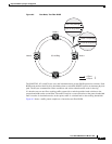
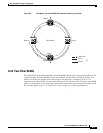
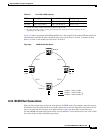
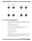
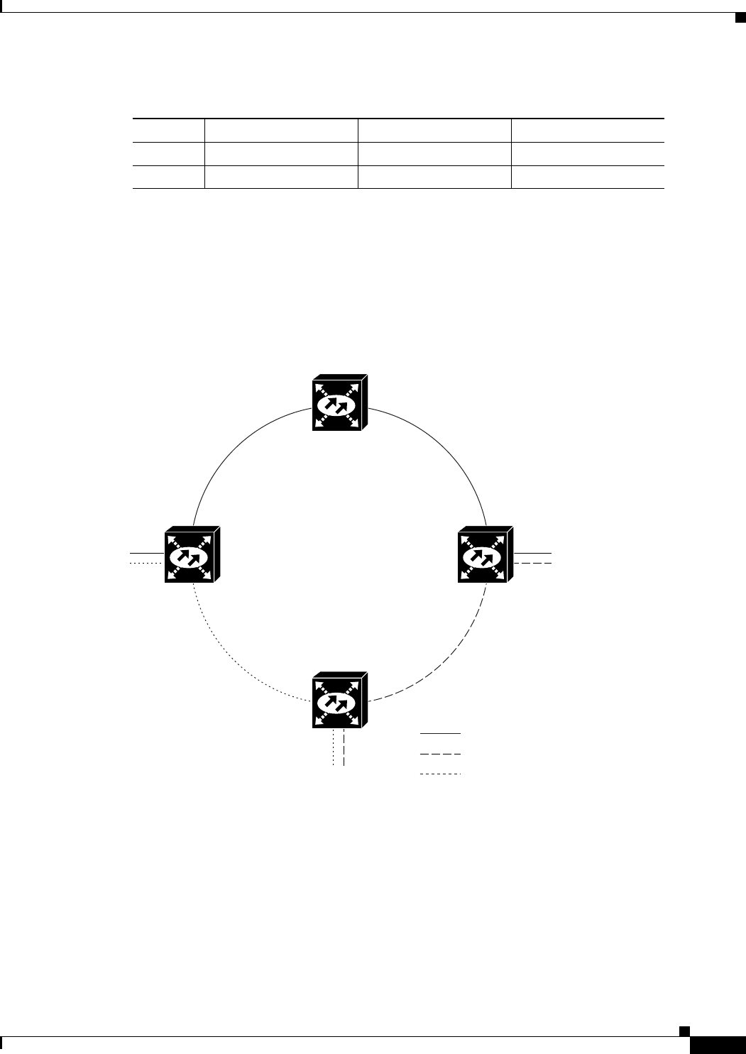
Figure 8-8 shows an example of BLSR bandwidth reuse. The same STS carries three different traffic sets
simultaneously on different spans around the ring: one set from Node 3 to Node 1, another set from
Node 1 to Node 2, and another set from Node 2 to Node 3.
Figure 8-8 BLSR Bandwidth Reuse
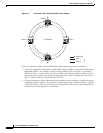
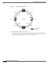
8.3.4 BLSR Fiber Connections
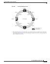
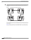
Plan your fiber connections and use the same plan for all BLSR nodes. For example, make the east port
the farthest slot to the right and the west port the farthest slot to the left. Plug fiber connected to an east
port at one node into the west port on an adjacent node. Figure 8-9 shows fiber connections for a
two-fiber BLSR with trunk (span) ports in Slot 4 (west) and Slot 12 (east). Refer to the Cisco ONS 15600
Procedure Guide for fiber connection procedures.
Table 8-2 Four-Fiber BLSR Capacity
OC Rate Working Bandwidth Protection Bandwidth Ring Capacity
OC-48 STS 1-48 (Fiber 1) STS 1-48 (Fiber 2) 48 x N
1
– PT
2
1. N equals the number of ONS 15600 nodes configured as BLSR nodes.
2. PT equals the number of STS-1 circuits passed through ONS 15600 nodes in the ring (capacity can vary
depending on the traffic pattern).
OC-192 STS 1-192 (Fiber 1) STS 1-192 (Fiber 2) 192 x N – PT
STS 1 STS 1
STS 1 STS 1
Node 0
Node 1
Node 2
Node 3
96662
= Node 3 – Node 1 traffic
= Node 1 – Node 2 traffic
= Node 2 – Node 3 traffic