Contents
viii
Cisco ONS 15600 Reference Manual, R7.2
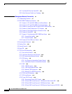
8.5.2 Two-Fiber BLSR to Four-Fiber BLSR 8-14
8.5.3 Add or Remove a Node from a Topology 8-14
CHAPTER
9
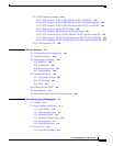
Management Network Connectivity 9-1
9.1 IP Networking Overview 9-1
9.2 ONS 15600 IP Addressing Scenarios 9-2
9.2.1 Scenario 1: CTC and ONS 15600s on the Same Subnet 9-2
9.2.2 Scenario 2: CTC and ONS 15600s Connected to Router 9-3
9.2.3 Scenario 3: Using Proxy ARP to Enable an ONS 15600 Gateway 9-4
9.2.4 Scenario 4: Default Gateway on CTC Computer 9-5
9.2.5 Scenario 5: Using Static Routes to Connect to LANs 9-6
9.2.6 Scenario 6: Using OSPF 9-8
9.2.7 Scenario 7: Provisioning the ONS 15600 Proxy Server 9-11
9.2.7.1 Firewall Not Enabled 9-12
9.2.7.2 Firewall Enabled 9-15
9.2.8 Scenario 8: Dual GNEs on a Subnet 9-17
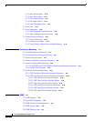
9.3 Provisionable Patchcords 9-19
9.4 Routing Table 9-20
9.5 External Firewalls 9-22
9.6 Open GNE 9-24
9.7 TCP/IP and OSI Networking 9-26
9.7.1 Point-to-Point Protocol 9-27
9.7.2 Link Access Protocol on the D Channel 9-28
9.7.3 OSI Connectionless Network Service 9-28
9.7.4 OSI Routing 9-31
9.7.4.1 End System-to-Intermediate System Protocol 9-32
9.7.4.2 Intermediate System-to-Intermediate System 9-32
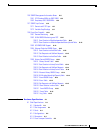
9.7.5 TARP 9-33
9.7.5.1 TARP Processing 9-34
9.7.5.2 TARP Loop Detection Buffer 9-35
9.7.5.3 Manual TARP Adjacencies 9-36
9.7.5.4 Manual TID to NSAP Provisioning 9-36
9.7.6 TCP/IP and OSI Mediation 9-36
9.7.7 OSI Virtual Routers 9-37
9.7.8 IP-over-CLNS Tunnels 9-38
9.7.8.1 Provisioning IP-over-CLNS Tunnels 9-39
9.7.8.2 IP-Over-CLNS Tunnel Scenario 1: ONS Node to Other Vendor GNE 9-40
9.7.8.3 IP-Over-CLNS Tunnel Scenario 2: ONS Node to Router 9-41
9.7.8.4 IP-Over-CLNS Tunnel Scenario 3: ONS Node to Router Across an OSI DCN 9-43


