


8-4
Cisco ONS 15600 Reference Manual, R7.2
Chapter 8 SONET Topologies and Upgrades
8.3.1 Two-Fiber BLSRs
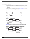
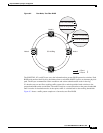
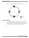
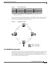
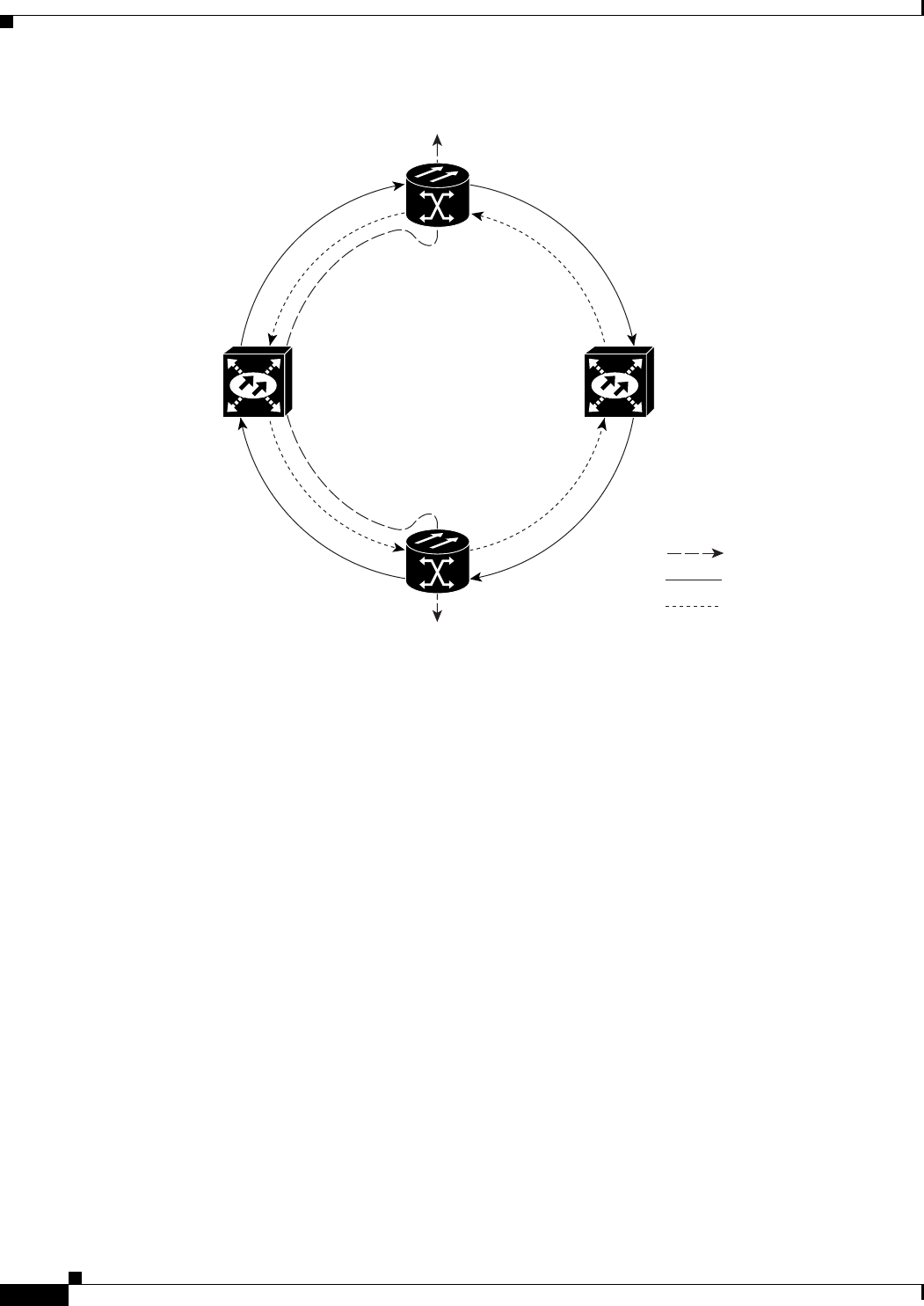
Figure 8-3 Four-Node, Two-Fiber BLSR Traffic Pattern Sample
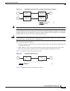
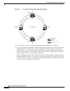
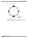
Figure 8-4 shows how traffic is rerouted following a line break between Node 0 and Node 3.
•
All circuits originating on Node 0 that carried traffic to Node 2 on Fiber 2 are switched to the protect
bandwidth of Fiber 1. For example, a circuit carrying traffic on STS-1 on Fiber 2 is switched to
STS-25 on Fiber 1. A circuit carried on STS-2 on Fiber 2 is switched to STS-26 on Fiber 1. Fiber 1
carries the circuit to Node 3 (the original routing destination). Node 3 switches the circuit back to
STS-1 on Fiber 2 where it is routed to Node 2 on STS-1.
•
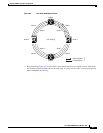
Circuits originating on Node 2 that normally carry traffic to Node 0 on Fiber 1 switch to the protect
bandwidth of Fiber 2 at Node 3. For example, a circuit carrying traffic on STS-2 on Fiber 1 switches
to STS-26 on Fiber 2. Fiber 2 carries the circuit to Node 0 where the circuit switches back to STS-2
on Fiber 1 and is then dropped to its destination.
Node 0
Node 1
Traffic flow
Node 2
Node 3 OC-48 Ring
Fiber 1
Fiber 2
96672