


2-18
Cisco ONS 15600 Reference Manual, R7.2
Chapter 2 Card Reference
2.7.2 OC192/STM64 SR/SH 4 Port 1310 Faceplate and Block Diagram
2.7.2 OC192/STM64 SR/SH 4 Port 1310 Faceplate and Block Diagram
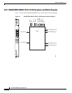
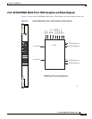
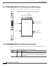
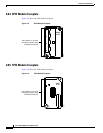
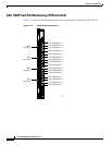
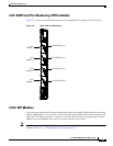
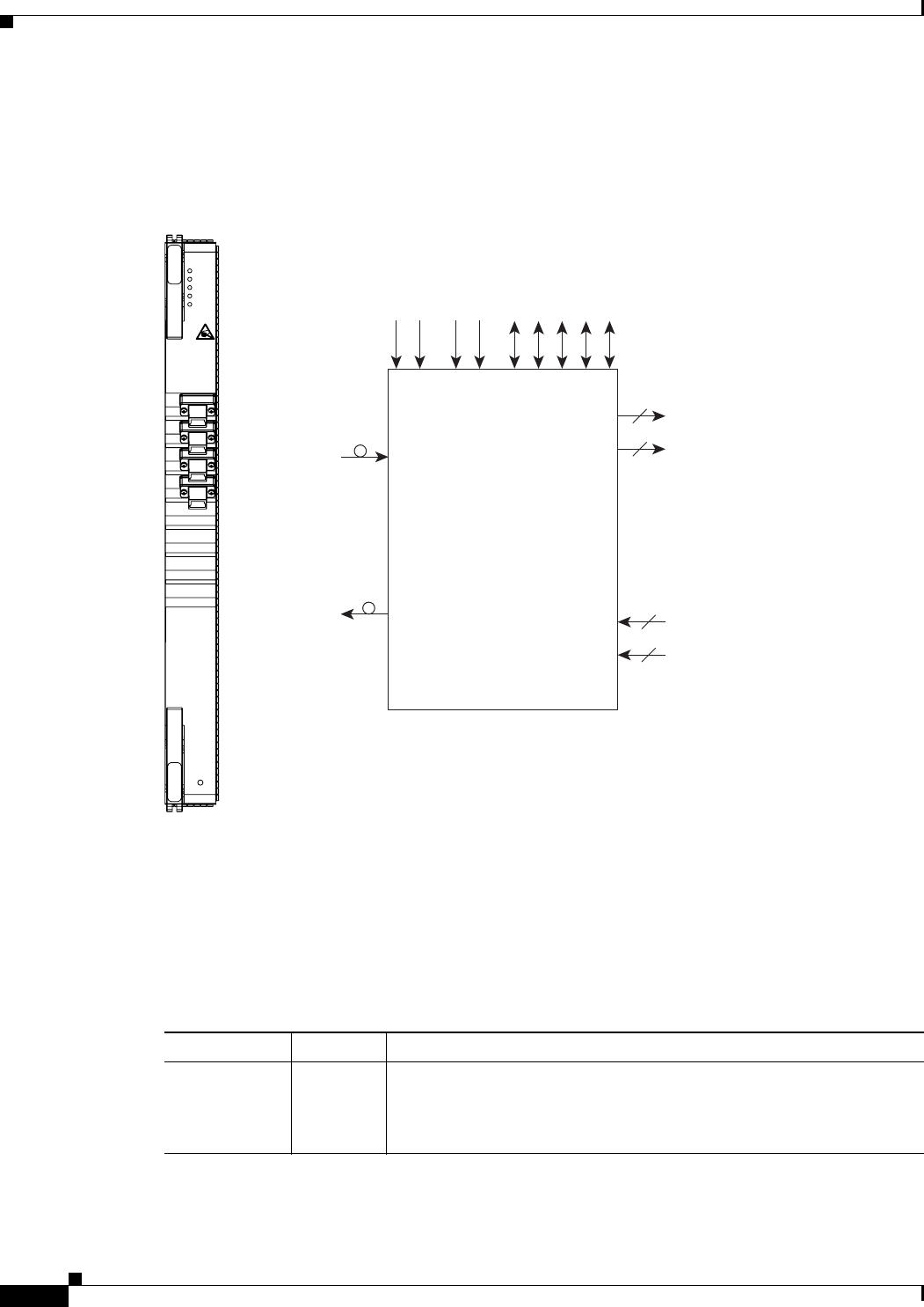
Figure 2-6 shows the OC192/STM64 SR/SH 4 Port 1310 faceplate and block diagram.
Figure 2-6 OC192/STM64 SR/SH 4 Port 1310 Faceplate and Block Diagram
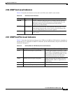
2.7.3 OC192/STM64 SR/SH 4 Port 1310 Card-Level Indicators
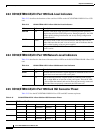
Table 2-16 describes the functions of the card-level LEDs on the OC192/STM64 SR/SH 4 Port 1310
card.
OC192/STM64
SR/SH 4 PORT
1310
98296
STAT
SRV
SD
SF
LASER ON
OC192
SCLAN A
SCLAN B
O&M B
sync 0
sync 1
C-STS-48 copy A
C-STS-48 copy B
C-STS-48 copy A
C-STS-48 copy B
Note: Each C-STS-192 is split into four
C-STS-48s for cross-connect purposes.
16
16
16
16
4 x OC-192
4 x OC-192
O&M A
I
2
C
–48V A
–48V B
Table 2-16 OC192/STM64 SR/SH 4 Port 1310 Card-Level Indicators
Indicator Color Description
STAT LED
Red Indicates a hardware fault; this LED is off during normal operation.
Replace the unit if the STAT LED persists. During diagnostics, the LED
flashes quickly during initialization and slowly during configuration
synchronization.