


8-10
Cisco ONS 15600 Reference Manual, R7.2
Chapter 8 SONET Topologies and Upgrades
8.3.4 BLSR Fiber Connections
Note
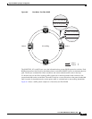
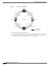
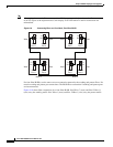
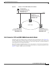
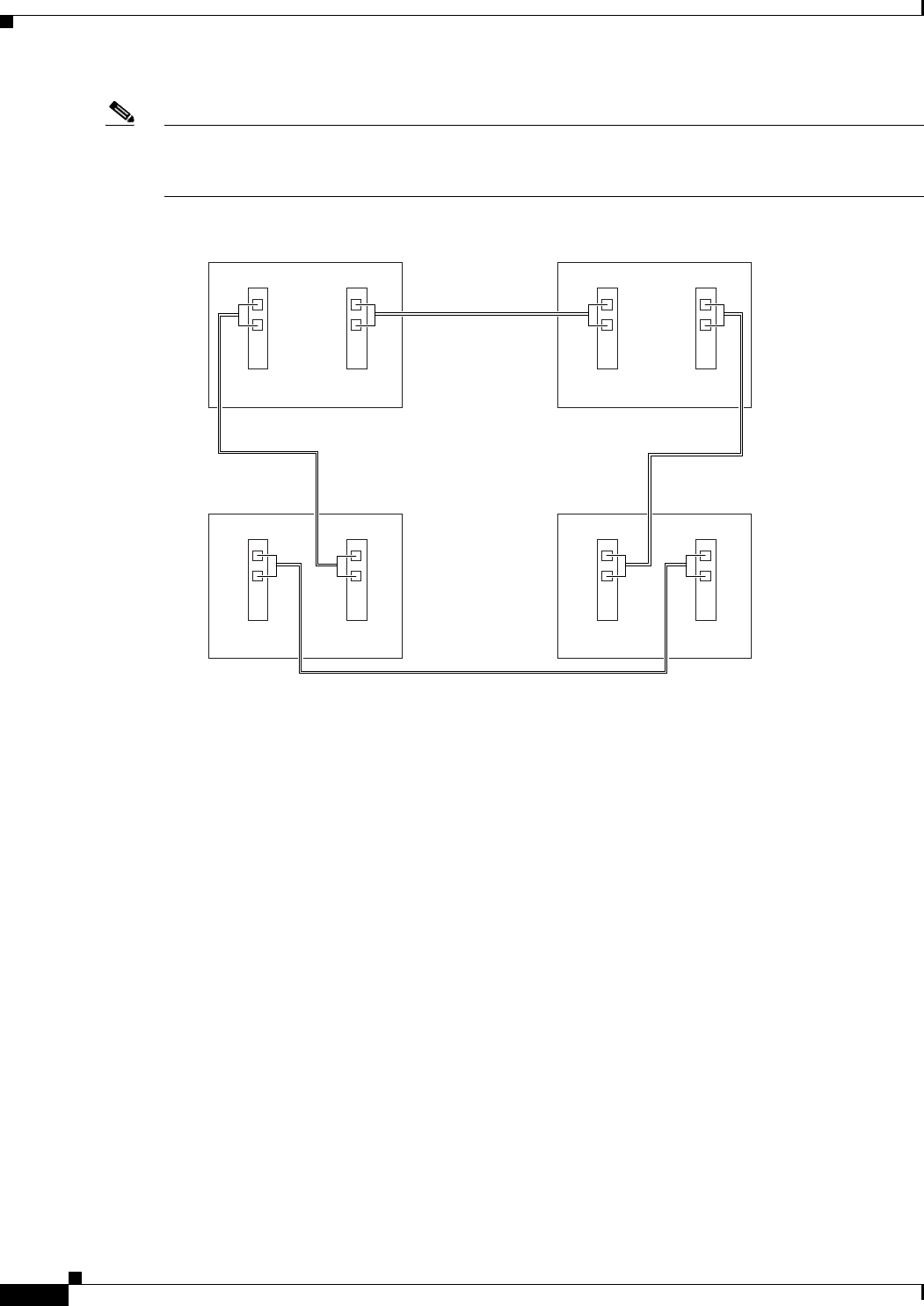
Always plug the transmit (Tx) connector of an OC-N port at one node into the receive (Rx) connector
of an OC-N port at the adjacent node. Cards display an SF LED when Tx and Rx connections are
mismatched.
Figure 8-9 Connecting Fiber to a Four-Node, Two-Fiber BLSR
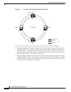
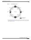
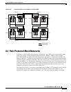
For four-fiber BLSRs, use the same east-west connection pattern for the working and protect fibers. Do
not mix working and protect port connections. The BLSR does not function if working and protect ports
are interconnected.
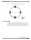
Figure 8-10 shows fiber connections for a four-fiber BLSR. Slot 2/Port 7 (west) and Slot 12/Port 11
(east) carry the working traffic. Slot 3/Port 1 (west) and Slot 13/Port 1 (east) carry the protect traffic.
96663
Node 1
West East
West East
West East
West East
Slot 4
Port 1
Tx
Rx
Slot 12
Port 3
Tx
Rx
Node 4
Slot 4
Port 1
Tx
Rx
Slot 12
Port 3
Tx
Rx
Node 2
Slot 4
Port 1
Tx
Rx
Slot 12
Port 3
Tx
Rx
Node 3
Slot 4
Port 1
Tx
Rx
Slot 12
Port 3
Tx
Rx