


Operating The T703 over the Serial I/O Ports Teledyne API T703 Calibrator Operation Manual
104
7. OPERATING THE T703 OVER THE SERIAL I/O
PORTS
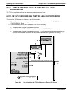
7.1. USING THE ANALYSER’S COMMUNICATION PORTS
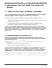
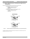
The T703 is equipped with two serial communication ports, labeled RS232 (male DB-9 connector) and COM2
(female DB-9 connector), a USB com port and an Ethernet port located on the rear panel.
The RS232 and COM2 ports operate similarly and give the user the ability to communicate with, issue
commands to, and receive data from the calibrator through an external computer system or terminal.
The RS-232 port (COM1) can also be configured to operate in single or RS-232 multidrop mode (option
62. See Section 5.2.2 and 7.3.
The COM2 p
ort can be configured for standard RS-232 operation or for half-duplex RS-485
communication. (Contact the factory for RS-485 communication configuration).
The Ethernet connector allows the analyzer to be connected to a network running TCP/IP or to the public
Internet if access is available. The network must have routers capable of operating at 10Base-T or 100Base-T.
DHCP is enabled by default (Section 7.5.1). This configuration is useful for quickly
getting an instrument up and
running on a network. However, for permanent Ethernet connections, a static IP address should be used
(Section 7.5.1.1).
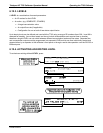
7.1.1. RS-232 DTE AND DCE COMMUNICATION
RS-232 was developed for allowing communications between data terminal equipment (DTE) and data
communication equipment (DCE). Basic data terminals always fall into the DTE category whereas modems are
always considered DCE devices.
Electronically, the difference between the DCE & DTE is the pin assignment of the Data Receive and Data
Transmit functions.
DTE devices receive data on pin 2 and transmit data on pin 3.
DCE devices receive data on pin 3 and transmit data on pin 2.
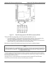
A switch located below the serial ports on the rear panel allows the user to switch between DTE (for use with
data terminals) or DCE (for use with modems). Since computers can be either DTE or DCE, check your
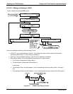
computer to determine which mode to use. Edit the Instrument and Gateway IP addresses and Subnet Mask to
the desired settings. Then, from the computer, enter the same information through an application such as
HyperTerminal.
The USB port is for optional direct communication between the calibrator and a desktop or laptop computer. This
configuration can be used when the COM2 port is not in use except for multidrop communication. When using
the USB com port, the baud rate must match between the computer and the calibrator; you may change either
one to match the other. To view the instrument’s baud rate, and change if desired, please refer to Section 7.1.3.
07223B DCN6378