


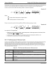
Theory of Operation Teledyne API T703 Calibrator Operation Manual
174
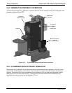
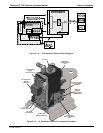
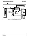
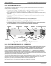
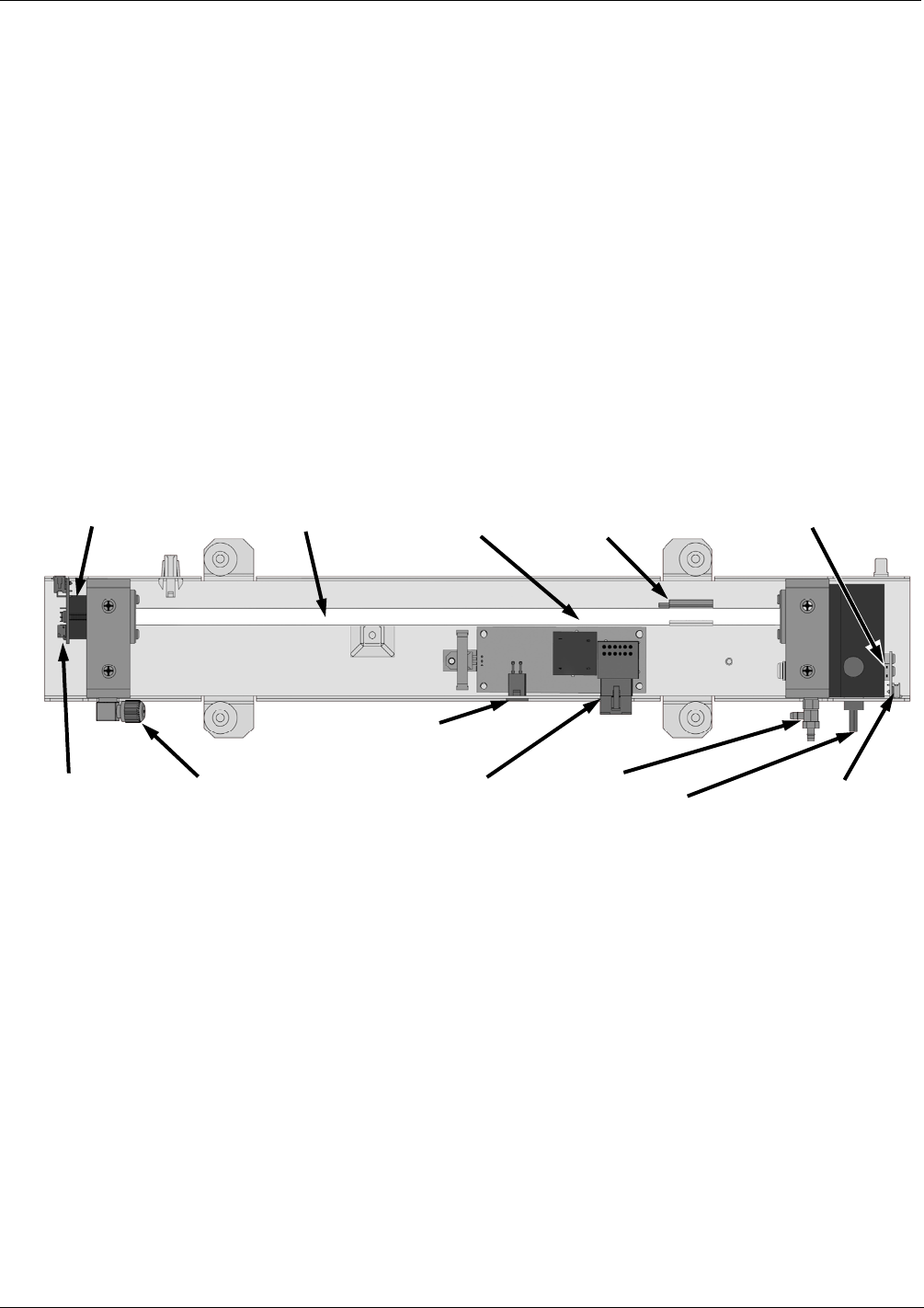
9.6.2. PHOTOMETER LAYOUT
The Photometer is where the absorption of UV light by ozone is measured and converted into a voltage. It
consists of several sub-assemblies:
A mercury-vapor UV lamp. This lamp is coated in a material that optically screens the UV radiation
output to remove the O
3
producing 185nm radiation. Only light at 254nm is emitted.
An AC power supply that supplies the current for starting and maintaining the plasma arc of the mercury
vapor lamp.
A thermistor and DC heater attached to the UV Lamp to maintain the Lamp at an optimum operating
temperature.
42 cm long quartz absorption tube.
A thermistor attached to the quartz tube for measuring sample gas temperature.
Gas inlet and outlet mounting blocks that rout sample gas into and out of the photometer.
The vacuum diode, UV detector that converts UV light to a DC current.
A preamplifier assembly, which convert the Detector’s current output into a DC Voltage then amplifies it
to a level readable by the A to D converter circuitry of the instrument’s motherboard
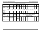
Absorption Tube
UV Lamp Heater
Control PCA
Sample Gas
Outlet
UV Lamp Power
Transformer
Power Connector
from
+15 VDC power supply
UV Lamp Power
Supply
(200 VAC @ 30 kHz)
Sam
p
le Gas Inlet UV Detector
Preamp PCA
UV Detector
Sample Gas
Thermistor
UV Lamp
UV Lamp Thermistor
(UV Lamp Heater Behind Thermistor)
Figure 9-20: O
3
Photometer Layout – Top Cover Removed
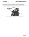
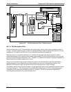
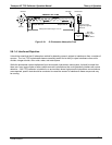
9.6.3. PHOTOMETER PNEUMATIC OPERATION
The flow of gas through the photometer is created by a small internal pump that pulls air though the instrument.
There are several advantages to this “pull through” configuration. Placing the pump down stream from the
absorption tube avoids problems caused by the pumping process heating and compressing the sample.
In order to measure accurately the presences of low concentrations of O
3
in the sample air it is necessary to
establish and maintain a relatively constant and stable volumetric flow of sample gas through the photometer.
The simplest way to accomplish this is by placing a flow control assembly containing a critical flow orifice directly
upstream of the pump but down stream from the absorption tube.
The critical flow orifice installed in the pump supply line is tuned to create a gas flow of 800 cm
3
/min. A pressure
sensor and a flow sensor, located on the O
3
generator / photometer pressure flow sensor PCA, monitor the
pressure and flow rate of the gas passing through the photometers absorption tube.
See Figures 9-18 and 9-19 for depictions of the gas flow related to the photometer.
07223B DCN6378