


Operating The T703 over the Serial I/O Ports Teledyne API T703 Calibrator Operation Manual
116
7.2. REMOTE ACCESS BY MODEM
The T703 can be connected to a modem for remote access. This requires a cable between the calibrator’s COM
port and the modem, typically a DB-9F to DB-25M cable (available from Teledyne API with part number
WR0000024).
Once the cable has been connected, check to make sure:
The DTE-DCE is in the DCE position.
The T703 COM port is set for a baud rate that is compatible with the modem,
The Modem is designed to operate with an 8-bit word length with one stop bit.
The MODEM ENABLE communication mode is turned ON (Mode 64, see Section 7.1.4).
Once this is completed, the appropriate setup command line for your modem can be entered into the calibrator.
The default setting for this feature is
AT Y0 &D0 &H0 &I0 S0=2 &B0 &N6 &M0 E0 Q1 &W0
This string can be altered to match your modem’s initialization and can be up to 100 characters long.
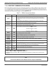
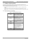
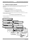
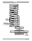
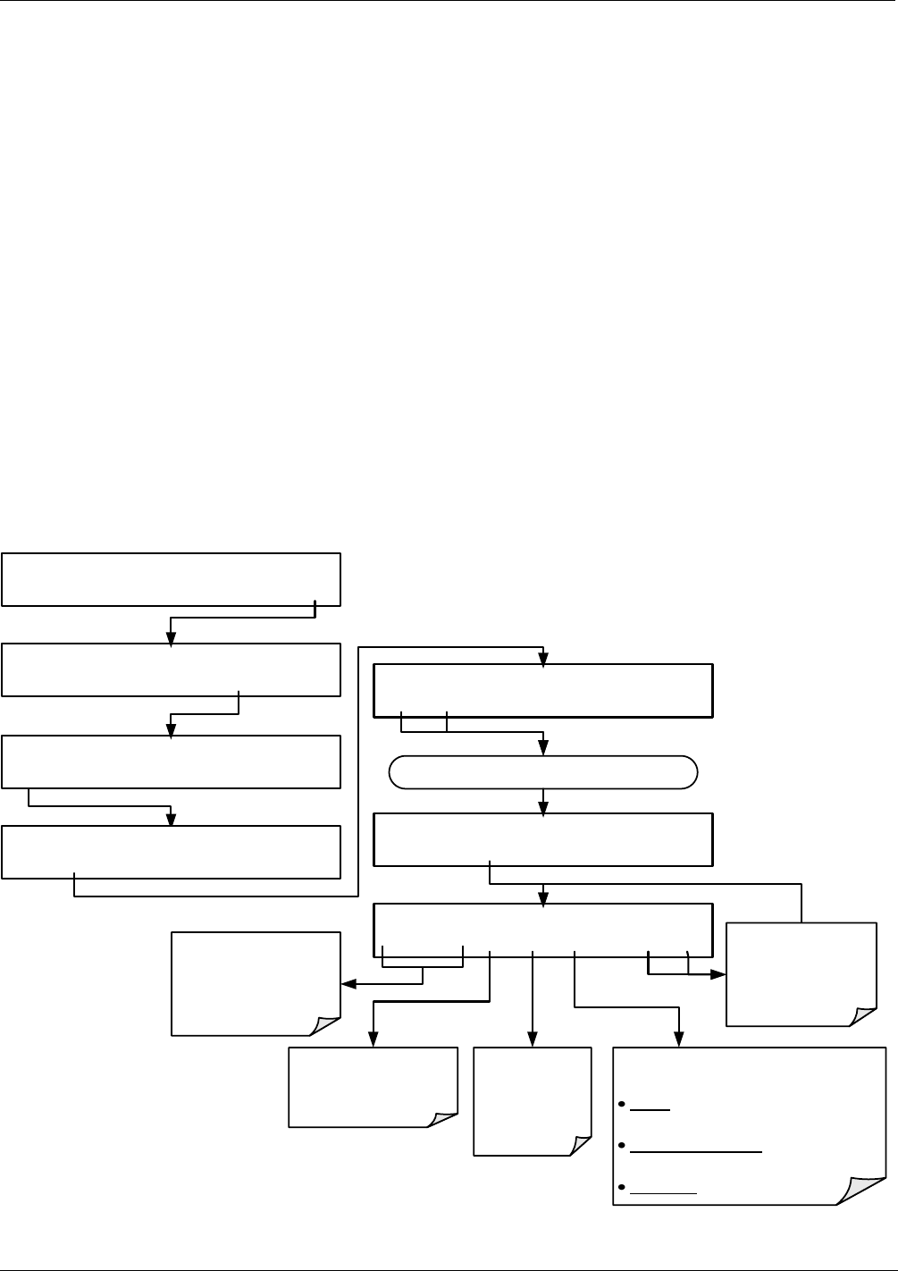
To change this setting press:
STANDBY ACT =STANDBY
<TST TST> GEN STBY SEQ SETUP
SETUP X.X PRIMARY SETUP MENU
O3 SEQ CFG CLK PASS MORE EXIT
SETUP X.X SECONDARY SETUP MENU
COMM VARS DIAG EXIT
SETUP X.X COMMUNICATIONS MENU
ID COM1 COM2 EXIT
SETUP X.X COM1 MODE:0
<SET SET> EDIT EXIT
SETUP X.X COM1 PORT INIT:AT Y0 &DO &H &I0
<SET SET> EDIT EXIT
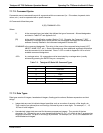
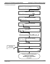
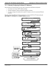
Continue pressing <SET or SET> until ...
SETUP X.X COM1 PORT INIT:AT Y0 &DO &H &I0
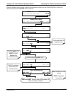
<CH CH> INS DEL [A] ENTR EXIT
EXIT discards the
new setting
ENTR accepts the
new setting
The <CH and CH>
keys move the cursor
left and right along the
text string
The INS and CH> key
inserts a new
character before the
cursor position
The DEL
deletes
character at
the cursor
position
Toggle this key to cycle through the
available character set:
Alpha: A-Z (Upper and Lower
Case);
Special Characters: space ’ ~ ! # $
% ^ & * ( ) - _ = +[ ] { } < > | ; : , . / ?
Numerals: 0-9
07223B DCN6378