


Teledyne API T703 Calibrator Operation Manual Getting Started
35
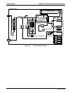
3.2.5. CONNECTING THE CONTROL OUTPUTS
The calibrator is equipped with 12 opto-isolated, digital control outputs. These outputs are activated by the
T703’s user-programmable, calibration sequences (see Section 6.5.1.6 for instructions on assigning the control
outputs to specific
calibration sequences)
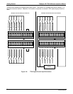
These outputs may be used to interface with devices that accept logic-level digital inputs, such as programmable
logic controllers (PLCs), dataloggers, or digital relays/valve drivers.
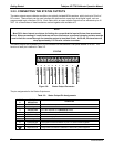
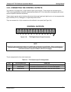
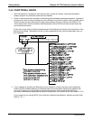
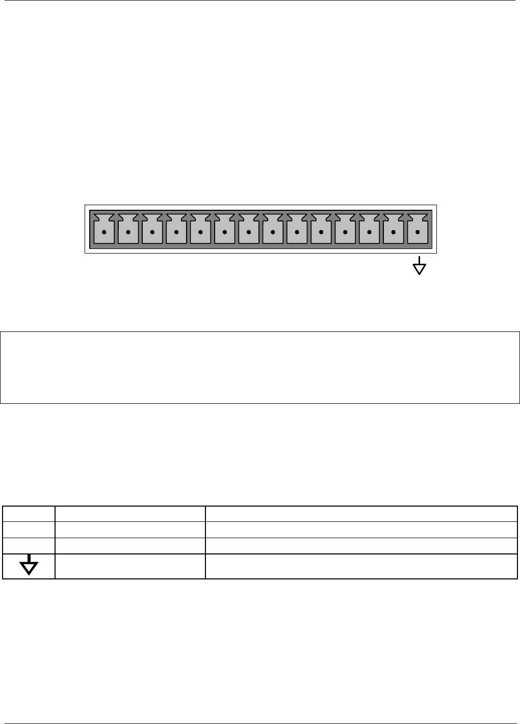
They are accessed via a 14-pin connector on the calibrator’s rear panel (see Figure 3-4).
CONTROL OUTPUTS
1 2 3 4 5 6 7 8 9 10 11 12 E
Figure 3-10: T703 Digital Control Output Connector
NOTE
Most PLCs have internal provisions for limiting the current the input will draw. When connecting to a
unit that does not have this feature, external resistors must be used to limit the current through the
individual transistor outputs to ≤50mA (120 Ω for 5V supply).
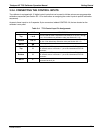
The pin assignments for the control outputs are:
Table 3-5: T703 Control Input Pin Assignments
PIN # STATUS DEFINITION CONDITION
1 - 12 Outputs 1 through 12 respectively Closed if the sequence or sequence step activating output is operating
E Emitter BUSS The emitters of the transistors on pins 1 to 8 are bussed together.
Digital Ground The ground level from the calibrator’s internal DC power supplies.
07223B DCN6378