Theory of Operation Teledyne API T703 Calibrator Operation Manual
172
PHOTOMETER
PRESSURE SENSOR
O
3
GEN / PHOTOMETER
PRESSURE / FLOW SENSOR PCA
O
3
GAS INPUT
PRESSURE SENSOR
REF/MEAS
Valve
On Back Panel
Chassis
GAS OUTPUT MANIFOLD
PHOTOMETER
OUTLET
TO ANALYZER
VENT
TO ANALYZER
PHOTOMETER
INLET
EXHAUST
PHOTOMETER
ZERO OUT
PHOTOMETER
ZERO IN
PHOTOMETER BENCH
PUMP
Flow Control
(800 cm
3
/min)
INTERNAL
VENT
Pressure
Regulator
Filter
DRY AIR
IN
ZERO AIR
IN
PUMP
blk
blk
blu
blu
orn
orn
orn
orn
red
pur
pur
grn
grn
yel
yel
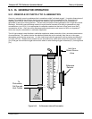
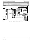
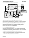
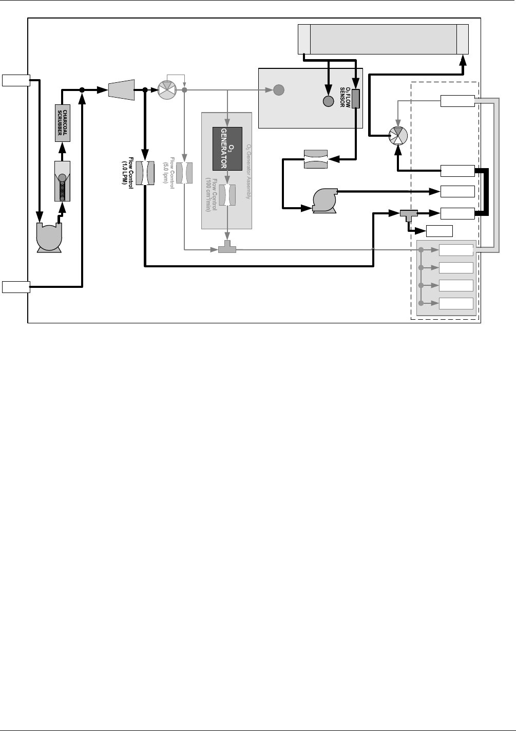
Figure 9-18: O
3
Photometer Gas Flow – Reference Cycle
9.6.1.3. The Absorption Path
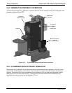
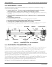
In the most basic terms, the T703 photometer uses a high energy, mercury vapor lamp to generate a beam of
UV light. This beam passes through a window of material specifically chosen to be both non-reactive to O
3
and
transparent to UV radiation at 254nm and into an absorption tube filled with sample gas.
Because ozone is a very efficient absorber of UV radiation the absorption path length required to create a
measurable decrease in UV intensity is short enough (approximately 42 cm) that the light beam is only required
to make one pass through the Absorption Tube. Therefore, no complex mirror system is needed to lengthen the
effective path by bouncing the beam back and forth.
Finally, the UV passes through a similar window at the other end of the absorption tube and is detected by a
specially designed vacuum diode that only detects radiation at or very near a wavelength of 254nm. The
specificity of the detector is high enough that no extra optical filtering of the UV light is needed.
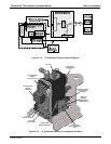
The detector reacts to the UV light and outputs a current signal that varies in direct relationship with the intensity
of the light shining on it. This current signal is amplified and converted to a 0 to 5 VDC voltage analog signal
voltage sent to the instrument’s motherboard where it is digitized. The CPU to be uses this digital data in
computing the concentration of O
3
in the absorption tube.
07223B DCN6378


