


Theory of Operation Teledyne API T703 Calibrator Operation Manual
154
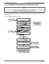
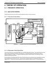
Data are generated by the various sub components of the T703 (e.g. flow data from the MFCs, O
3
concentration
from the optional photometer). Analog signals are converted into digital data by a unipolar, analog-to-digital
converter, located on the motherboard.
A variety of sensors report the physical and operational status of the calibrator’s major components, again
through the signal processing capabilities of the motherboard. These status reports are used as data for the
concentration calculations and as trigger events for certain control commands issued by the CPU. They are
stored in memory by the CPU and in most cases can be viewed but the user via the front panel display.
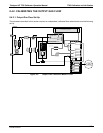
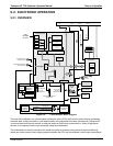
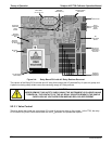
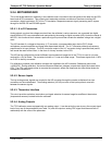
9.2.2. CENTRAL PROCESSING UNIT (CPU)
The unit’s CPU card (Figure 9-3) is installed on the motherboard located inside the rear panel. It is a low power
(5 VDC, 720mA max), high performance, Vortex 86SX-based microcomputer running Windows CE. Its operation
and assembly conform to the PC-104 specification and features the following:
Figure 9-3: T703 CPU Board Annotated
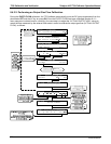
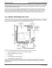
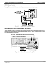
The CPU communicates with the user and the outside world in a variety of manners:
Through the calibrator’s front panel LCD touchscreen interface;
RS 232 and RS485 serial I/O channels;
Via Ethernet;
Various digital and analog outputs, and
A set of digital control input channels.
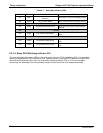
Finally, the CPU issues commands via a series of relays and switches (also over the I
2
C bus) located on a
separate printed circuit assembly to control the function of key electromechanical devices such as heaters,
motors and valves.
07223B DCN6378