


General Troubleshooting & Repair Teledyne API T703 Calibrator Operation Manual
190
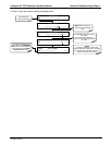
5. Follow the procedures defined in Section 3.4.4 to confirm that the calibrator’s vital functions are working
(power supplies, CPU, relay PCA, keyboard, PMT cooler, etc.).
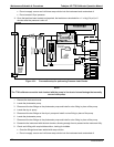
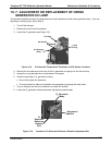
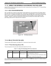
See Figure 3-5 for general layout of components and sub-
assemblies in the calibrator.
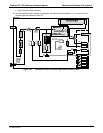
See the wiring interconnect diagram and interconnect list in Appendix D.
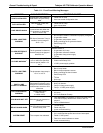
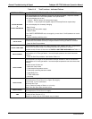
11.1.1. FAULT DIAGNOSIS WITH WARNING MESSAGES
The most common and/or serious instrument failures will result in a warning message being displayed on the
front panel. Table 11-1 lists warning messages, along with their meaning and recommended corrective action.
It should be no
ted that more than two or three warning messages occurring at the same time is often an
indication that some fundamental sub-system (power supply, relay PCA, motherboard) has failed rather than an
indication of the specific failures referenced by the warnings. In this case, it is recommended that proper
operation of power supplies (See Section 11.4.3), the relay PCA (See Section 11.4.7), and the motherboard
(See Sectio
n
11.4.9) be confirmed before addressing the spec
ific warning messages.
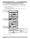
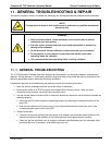
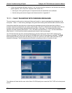
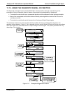
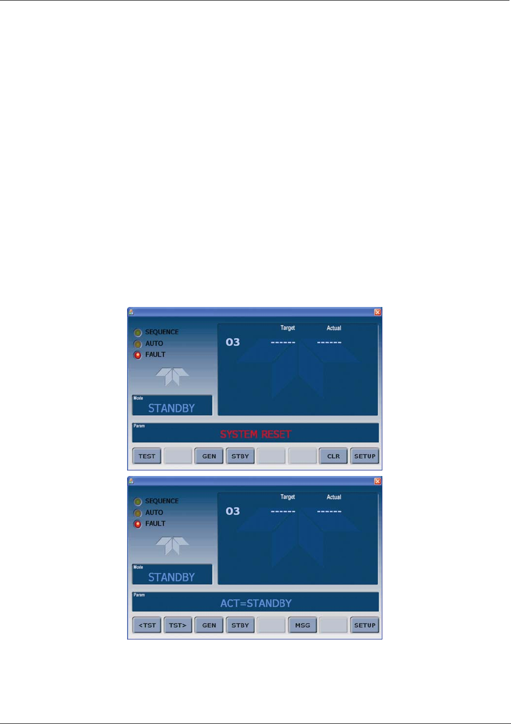
The T703 will alert the user that a Warning Message is active by flashing the FAULT LED, displaying the
Warning message in the Param field along with the CLR button (press to clear Warning message). The MSG
button displays if there is more than one warning in queue or if you are in the TEST menu and have not yet
cleared the message. The following display/touchscreen examples provide an illustration of each:
The calibrator will also alert the user via the Serial I/O COM port(s) and cause the FAULT LED on the front panel
to blink.
07223B DCN6378