


Teledyne API T703 Calibrator Operation Manual T703 Calibration and Verification
147
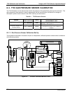
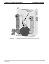
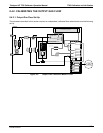
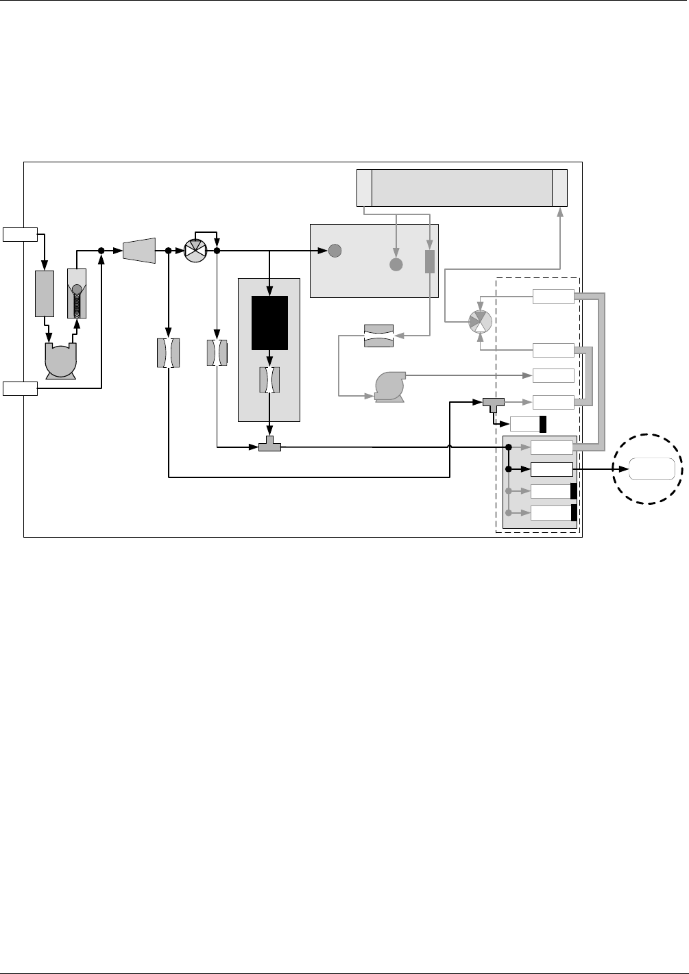
8.4.2. CALIBRATING THE OUTPUT GAS FLOW
8.4.2.1. Output Gas Flow Set Up
The procedure described in this section requires an independent, calibrated flow meter/monitor and the following
set up:
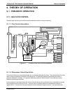
PHOTOMETER
PRESSURE SENSOR
O
3
GEN / PHOTOMETER
PRESSURE / FLOW SENSOR PCA
O
3
GAS INPUT
PRESSURE SENSOR
O
3
FLOW
SENSOR
O
3
Generator Assembly
O
3
GENERATOR
REF/MEAS
Valve
On Back Panel
Chassis
GAS OUTPUT MANIFOLD
PHOTOMETER
OUTLET
TO ANALYZER
VENT
TO ANALYZER
DRY AIR
IN
ZERO AIR
IN
PHOTOMETER
INLET
EXHAUST
PHOTOMETER
ZERO OUT
PHOTOMETER
ZERO IN
PHOTOMETER BENCH
OFF
INTERNAL
VENT
Flow Control
(5.0 lpm)
Pressure
Regulator
CHARCOAL
SCRUBBER
Filter
PUMP
Flow Control
(1.0 LPM)
FLOW
METER
CAP
CAP
CAP
Flow Control
(100 cm
3
/min)
Flow Control
(800 cm
3
/min)
Figure 8-5: Output Flow Calibration Monitor Point
07223B DCN6378