


Operating the T703 Calibrator Teledyne API T703 Calibrator Operation Manual
82
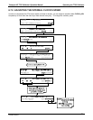
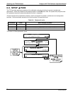
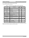
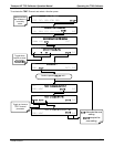
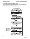
6.9.1.2. Selecting a TEST Channel Function to Output
The Test Functions available to be reported are:
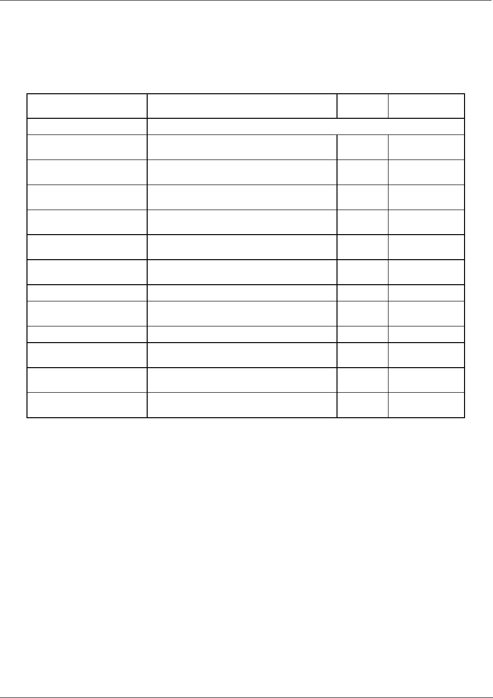
Table 6-8: Test Channels Functions Available on the T703’s Analog Output
TEST CHANNEL DESCRIPTION ZERO FULL SCALE
NONE TEST CHANNEL IS TURNED OFF
O3 PHOTO MEAS
The raw output of the photometer during its
measure cycle
0 mV 5000 mV*
O3 PHOTO REF
The raw output of the photometer during its
reference cycle
0 mV 5000 mV*
O3 GEN REF
The raw output of the O
3
generator’s
reference detector
0 mV 5000 mV*
OUTPUT FLOW
The gas flow being output through the CAL
GAS outlets on the back of the instrument
0 cm
3
/min 5,000 cm
3
/min
REGULATOR PRESSURE
The gas pressure measured by the O
3
generator pressure sensor
0 PSIG 105 PSIG
SAMPLE PRESSURE
The pressure of gas in the photometer
absorption tube
0 "Hg 40 "Hg-In-A
SAMPLE FLOW
The gas flow rate through the photometer 0 cm
3
/min 1000 cc
3
/min
SAMPLE TEMP
The temperature of gas in the photometer
absorption tube
0 C 70 C
PHOTO LAMP TEMP
The temperature of the photometer UV lamp
0 CC 70 C
O3 LAMP TEMP
The temperature of the O
3
generator’s UV
lamp
0 mV 5000 mV
CHASSIS TEMP
The temperature inside the T703’s chassis
(same as BOX TEMP)
0 C 70 C
O3 PHOTO CONC
The current concentration of O
3
being
measured by the photometer.
0 C
1 ppm
Once a function is selected, the instrument not only begins to output a signal on the analog output, but also adds
TEST to the list of Test Functions viewable via the Front Panel Display.
07223B DCN6378