


Teledyne API T703 Calibrator Operation Manual T703 Calibration and Verification
145
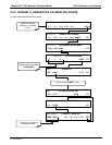
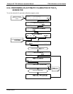
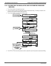
8.4. T703 GAS FLOW CALIBRATION
The T703 has two gas flow characteristics that affect its performance: the flow of gas thought the sample
chamber of the instrument’s photometer and the total gas flow being output. While both are stored in the
calibrator’s memory and used to compensate the final concentration calculations for changes in atmospheric
pressure, they are calculated quite differently.
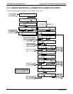
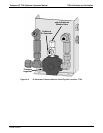
PHOTOMETER SAMPLE GAS FLOW RATE:
This flow rate is measured directly by a flow sensor located pressure / flow sensor PCA. A slope factor, stored
in the calibrator’s memory the last time a PHOTO FLOW calibration operation (see Section 8.4.1) was
perfo
rmed, is
and applied to the reading from that sensor.
The calculated photometer sample gas flow value is viewable on the instrument’s front panel using the PHOTO
FLOW test function and can be output via the T703’s TEST CHANNEL output using the SAMPLE FLOW
function.
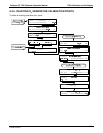
OUTPUT GAS FLOW RATE:
This flow rate is calculated by applying a separate slope factor, also stored in the calibrator’s memory, to an
interpolated valued based on the following table of internal gas pressure as measured by the O
3
gas input
pressure sensor. The output-flow slope value is determined by performing an OUPUT FLOW calibration
operation (see Section 8.4.2).
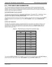
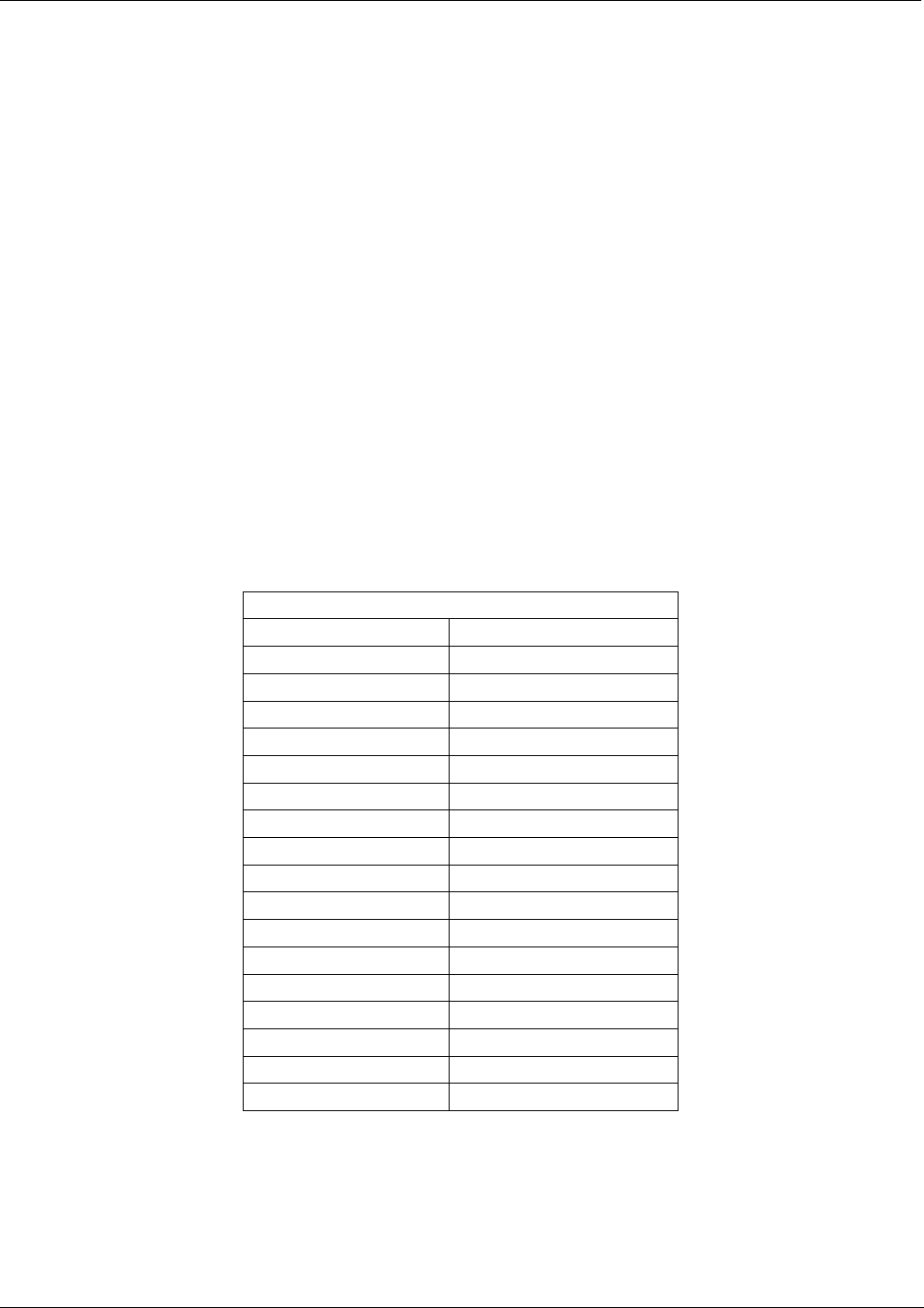
Table 8-2:
T703 G
as Pressure to Output Flow conversion Table
T703 REGULATOR PRESSURE TO OUTPUT FLOW
PSIG LPM
0 0.000
1 0.676
2 1.214
3 1.659
4 2.071
5 2.463
6 2.816
7 3.178
8 3.536
9 3.851
10 4.166
15 5.744
20 7.282
25 8.755
30 10.254
35 11.695
40 13.146
The calculated OUTPUT FLOW value is viewable on the instrument’s front panel using the OUTPUT FLOW test
function and can be output via the T703’s TEST CHANNEL using the OUTPUT FLOW function.
07223B DCN6378