


General Troubleshooting & Repair Teledyne API T703 Calibrator Operation Manual
202
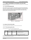
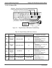
11.4.7. RELAY PCA
The Relay PCA can be most easily checked by observing the condition of the status LEDs located along its
upper edge (see Section 11.3.2 and Figure 11-3: Relay PCA Status LEDS Used for Troubleshooting), and using
the SIGNAL I/
O submenu under the DIAG menu (see Section 11.1.3) to toggle each LED ON or OFF.
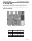
If D1 on the Relay PCA is flashing a
nd the status indicator for the output in question (Pump power, Heater
power, Valve Drive, etc.) toggles properly using the Signal I/O function, then the associated control device on the
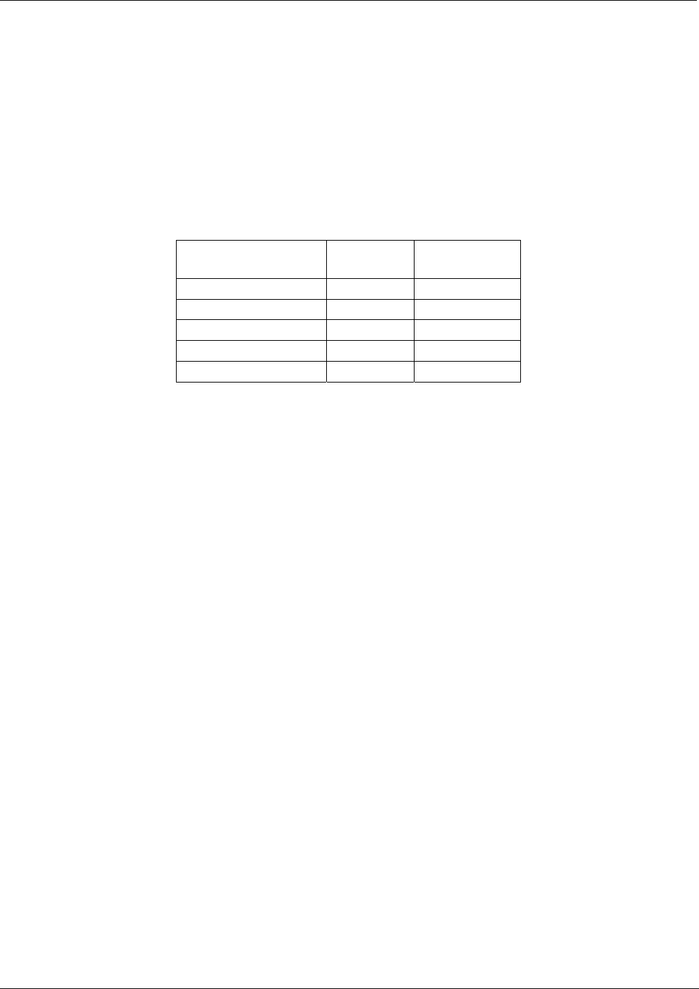
Relay PCA is bad. Several of the control devices are in sockets and can be easily replaced. The table below
lists the control device associated with a particular function.
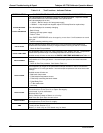
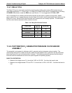
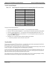
Table 11-8: Relay PCA Control Devices
FUNCTION
CONTROL
DEVICE
IN SOCKET
UV Lamp Heater Q2 No
O
3
Gen Heater Q3 No
All Valves U5 Yes
AC Dry air Pump K1 No
DC Photometer Pump U1 No
11.4.8. PHOTOMETER O
3
GENERATOR PRESSURE /FLOW SENSOR
ASSEMBLY
This assembly is only present in calibrators with O
3
generator and/or photometer options installed. The
pressure/flow sensor PCA, located at the rear of the instrument between the O
3
generator and the photometer
pump (see Figure 3-5) can be checked with a Voltmeter. The following pr
ocedure assumes that the wiring is
intact and that the motherboard as well as the power supplies are operating properly:
BASIC PCA OPERATION:
Measure the voltage across C1 it should be 5 VDC ± 0.25 VDC. If not then the board is bad
Measure the voltage between TP2 and TP1 C1 it should be 1o VDC ± 0.25 VDC. If not then the board is
bad.
07223B DCN6378