


Getting Started Teledyne API T703 Calibrator Operation Manual
32
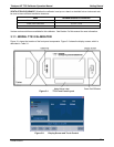
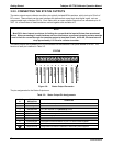
3.2.3. CONNECTING THE STATUS OUTPUTS
The status outputs report calibrator conditions via optically isolated NPN transistors, which sink up to 50 mA of
DC current. These outputs can be used interface with devices that accept logic-level digital inputs, such as
programmable logic controllers (PLCs). Each Status bit is an open collector output that can withstand up to 40
VDC. All of the emitters of these transistors are tied together and available at D.
NOTE
Most PLCs have internal provisions for limiting the current that the input will draw from an external
device. When connecting to a unit that does not have this feature, an external dropping resistor must be
used to limit the current through the transistor output to less than 50 mA. At 50 mA, the transistor will
drop approximately 1.2V from its collector to emitter.
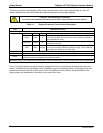
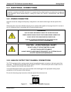
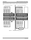
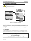
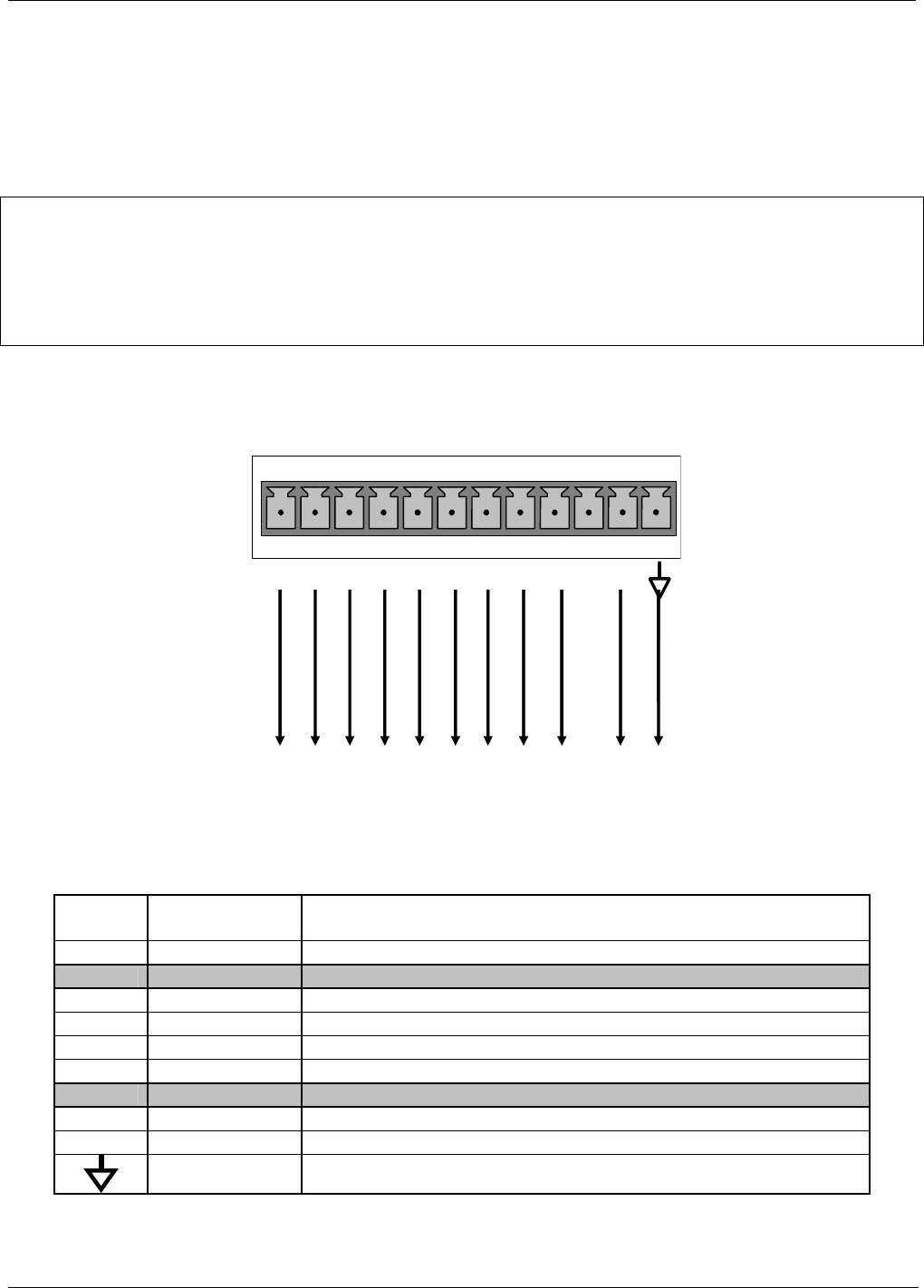
The status outputs are accessed via a 12-pin connector on the calibrator’s rear panel labeled STATUS. The
function of each pin is defined in Table 3-3.
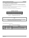
STATUS
1 2 3 4 5 6 7 8 D +
SYSTEM OK
CAL ACTIVE
POWER OK
DIAG
TEMP ALARM
PRESS ALARM
Unassigned
Unassigned
EMITTER BUSS
+ 5 VDC
CALIBRATOR
INRTERNAL GROUND
Figure 3-8: Status Output Connector
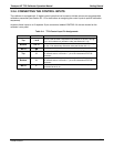
The pin assignments for the Status Outputs are:
Table 3-3: Status Output Pin Assignments
OUTPUT
#
STATUS
DEFINITION
CONDITION
1
SYSTEM OK
On, if no faults are present.
2 Unassigned
3
CAL ACTIVE On if the calibrator is in GENERATE mode
4
DIAG On if the calibrator is in DIAGNOSTIC mode
5
TEMP ALARM
On whenever a temperature alarm is active.
6
PRESS ALARM
On whenever gas pressure alarm is active
7 & 8 Unassigned
D Emitter BUSS The emitters of the transistors on pins 1 to 8 are bussed together.
+ DC POWER + 5 VDC
Digital Ground The ground level from the calibrator’s internal DC power supplies.
07223B DCN6378