


General Troubleshooting & Repair Teledyne API T703 Calibrator Operation Manual
214
11.7. TROUBLE SHOOTING THE OPTIONAL O
3
GENERATOR
The only significant components of the O
3
generator that might reasonable malfunction is the power supply
assembly for the UV source lamp and the lamp itself.
11.7.1. CHECKING THE UV SOURCE LAMP POWER SUPPLY
NOTE
A schematic and physical diagram of the Lamp Power Supply can be found in Appendix D.
WARNING
Hazardous voltage present - use caution.
It is not always possible to determine with certainty whether a problem is the result of the UV Lamp or the Lamp
Power Supply, however, the following steps will provide a reasonable confidence test of the Lamp Power
Supply.
1. Make sure the calibrator is in STANDBY mode.
2. Unplug the cable connector at P1 on the Lamp Power Supply and confirm that +15VDC is present
between Pins 1 and 2 on the cable connector.
3. If this voltage is incorrect, check the DC test points on the relay PCA as described in Section 11.4.3.
4.
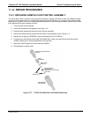
Remove the
cover of the photometer and check for the presence of the following voltages on the UV
lamp power supply PCA (see Figure 9-20):
+80
0 mVDC ± 10 mVDC between TP1 and TP4 (grnd)
If this voltage is incorrect, either the UV lamp power supply PCA is faulty or the I
2
C bus is not
communicating with the UV lamp power supply PCA.
+5VDC between TP3 and TP4 (grnd)
If this voltages is less than 4.8 or greater than 5.25 either the 5 VDC power supply or the UV lamp
power supply PCA are faulty.
If the above voltages check out, it is more likely that a problem is due to the UV Lamp than due to the
Lamp Power Supply.
Replace the Lamp and if the problem persists, replace the Lamp Power Supply.
07223B DCN6378