


Getting Started Teledyne API T703 Calibrator Operation Manual
30
PHOTOMETER
PRESSURE SENSOR
O
3
GEN / PHOTOMETER
PRESSURE / FLOW SENSOR PCA
O
3
GAS INPUT
PRESSURE SENSOR
O
3
FLOW
SENSOR
O
3
Generator Assembly
O
3
GENERATOR
Flow Control
(100 cm
3
/min)
REF/MEAS
Valve
On Back Panel
Instrument Chassis
GAS OUTPUT MANIFOLD
PHOTOMETER
OUTLET
TO ANALYZER
VENT
TO ANALYZER
DRY AIR
IN
ZERO AIR
IN
PHOTOMETER
INLET
EXHAUST
PHOTOMETER
ZERO OUT
PHOTOMETER
ZERO IN
PHOTOMETER BENCH
PUMP
Flow Control
(800 cm
3
/min)
INTERNAL
VENT
Flow Control
(5.0 lpm)
Pressure
Regulator
Filter
PUMP
Flow Control
(1.0 to 2.0 LPM)
blk
CHARCOAL
SCRUBBER
blk
blu
blu
orn
orn
orn
orn
red
red
pur
pur
grn
grn
yel
yel
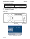
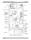
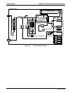
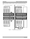
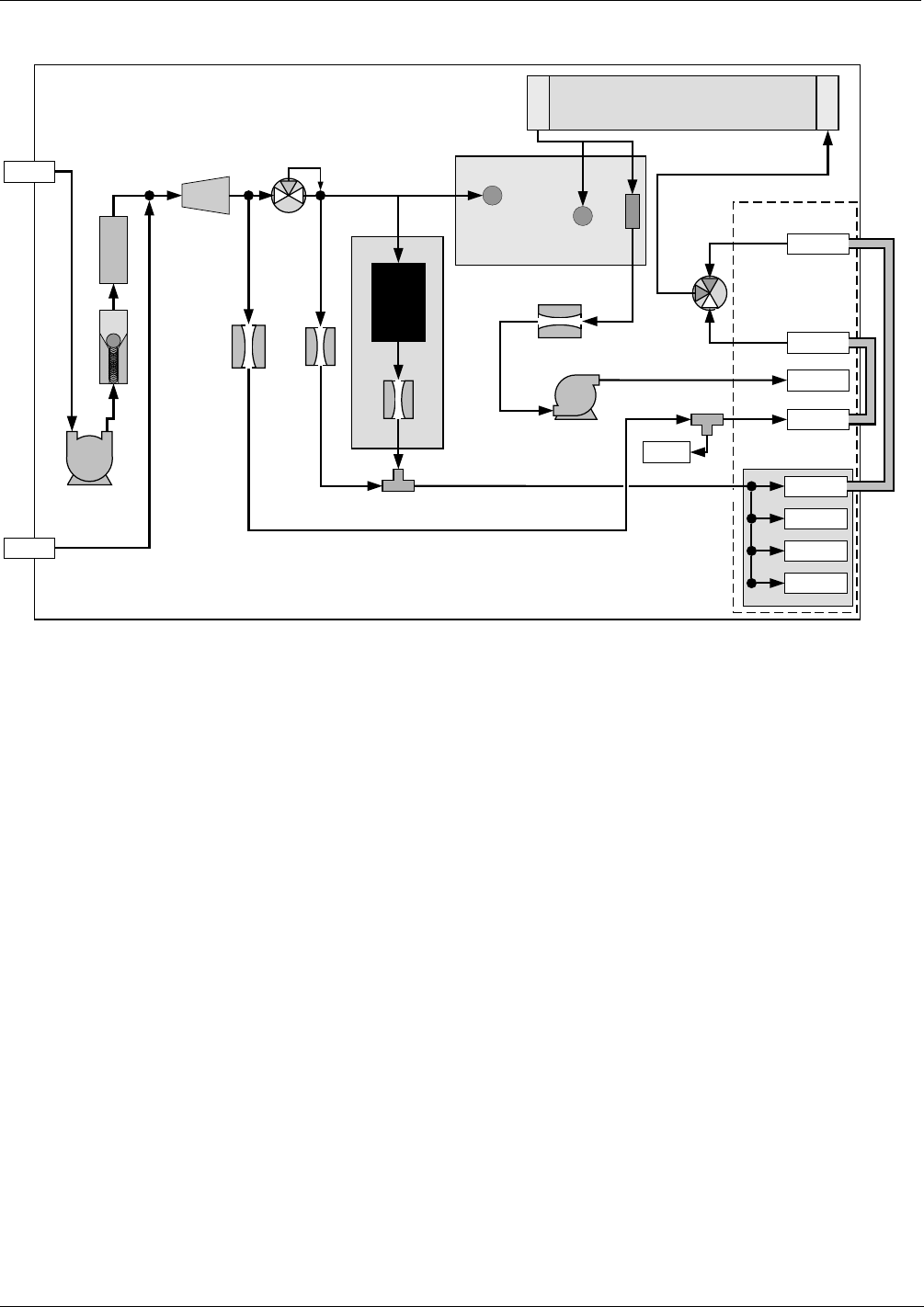
Figure 3-6: T703 Pneumatic Diagram
07223B DCN6378