


Teledyne API T703 Calibrator Operation Manual Theory of Operation
151
9. THEORY OF OPERATION
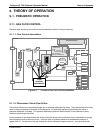
9.1. PNEUMATIC OPERATION
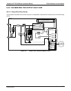
9.1.1. GAS FLOW CONTROL
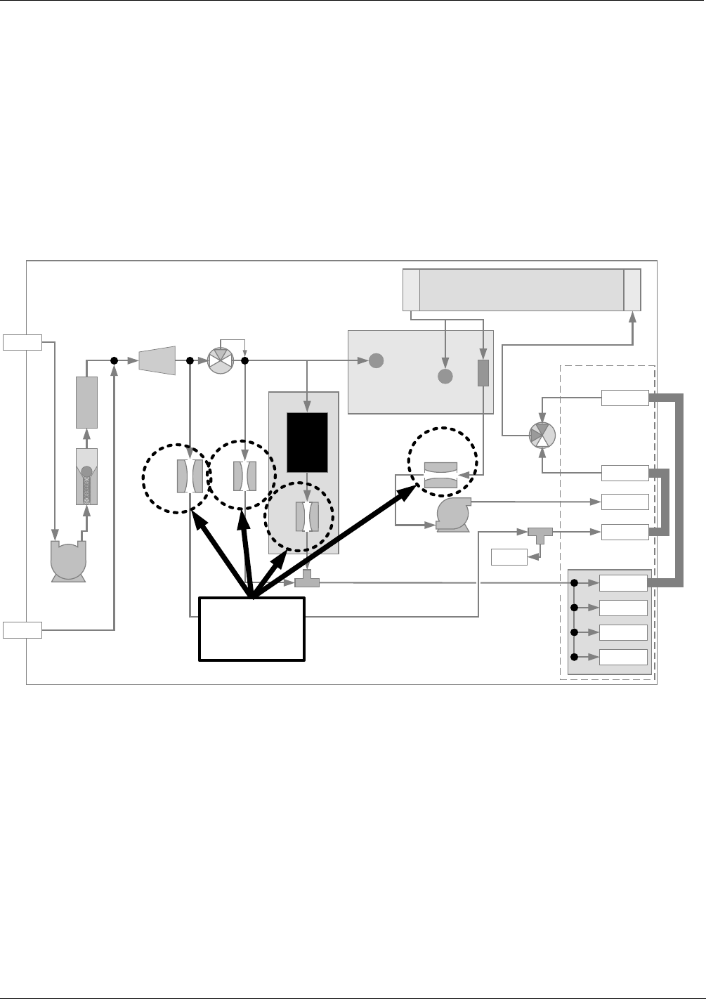
Gas flow rates are set by various flow control assemblies located in the gas stream(s).
9.1.1.1. Flow Control Assemblies
PHOTOMETER
PRESSURE SENSOR
O
3
GEN / PHOTOMETER
PRESSURE / FLOW SENSOR PCA
O
3
GAS INPUT
PRESSURE SENSOR
O
3
FLOW
SENSOR
O
3
Generator Assembly
O
3
GENERATOR
Flow Control
(100 cm
3
/min)
REF/MEAS
Valve
On Back Panel
Chassis
GAS OUTPUT MANIFOLD
PHOTOMETER
OUTLET
TO ANALYZER
VENT
TO ANALYZER
DRY AIR
IN
ZERO AIR
IN
PHOTOMETER
INLET
EXHAUST
PHOTOMETER
ZERO OUT
PHOTOMETER
ZERO IN
PHOTOMETER BENCH
PUMP
Flow Control
(800 cm
3
/min)
INTERNAL
VENT
Flow Control
(5.0 lpm)
Pressure
Regulator
Filter
PUMP
Flow Control
(1.0 to 2.0 LPM)
blk
CHARCOAL
SCRUBBER
blk
blu
blu
orn
orn
orn
orn
red
red
pur
pur
grn
grn
yel
yel
FLOW
CONTROL
ASSEMBLIES
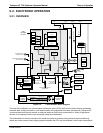
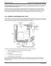
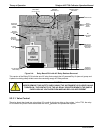
Figure 9-1: Location of Gas Flow Control Assemblies
9.1.1.2. Photometer Critical Flow Orifice
Critical flow orifices are a remarkably simple way to regulate stable gas flow rates. They operate without moving
parts by taking advantage of the laws of fluid dynamics. By restricting the flow of gas though the orifice, a
pressure differential is created. This pressure differential combined with the action of the calibrator’s pump
draws the gas through the orifice.
As the pressure on the downstream side of the orifice (the pump side) continues to drop, the speed that the gas
flows though the orifice continues to rise. Once the ratio of upstream pressure to downstream pressure is
greater than 2:1, the velocity of the gas through the orifice reaches the speed of sound. As long as that ratio
07223B DCN6378