


T703 Calibration and Verification Teledyne API T703 Calibrator Operation Manual
130
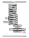
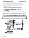
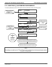
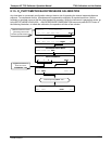
Figure 8-2: Set up for Verifying Optional O
3
Photometer Using an External O
3
Generator
NOTE
The manifolds as shown in the above drawing are oriented to simplify the drawing.
All unused ports should be capped.
A Minimum of 1.1 LPM is required for the external zero air source
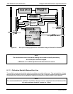
8.1.1.1. Calibration Manifold Exhaust/Vent Line
The manifold’s excess gas should be vented to a suitable vent outside of the room. This vent should be of large
enough internal diameter to avoid any appreciable pressure drop, and it must be located sufficiently downstream
of the output ports to assure that no ambient air enters the manifold due to eddy currents or back diffusion.
NOTE
It is recommended that the calibration manifold’s exhaust vent have a minimum internal diameter of 3/8
inch and a maximum length of 3 meters (or 10 feet)
07223B DCN6378