


General Troubleshooting & Repair Teledyne API T703 Calibrator Operation Manual
206
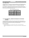
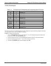
11.4.9.4. Control Inputs
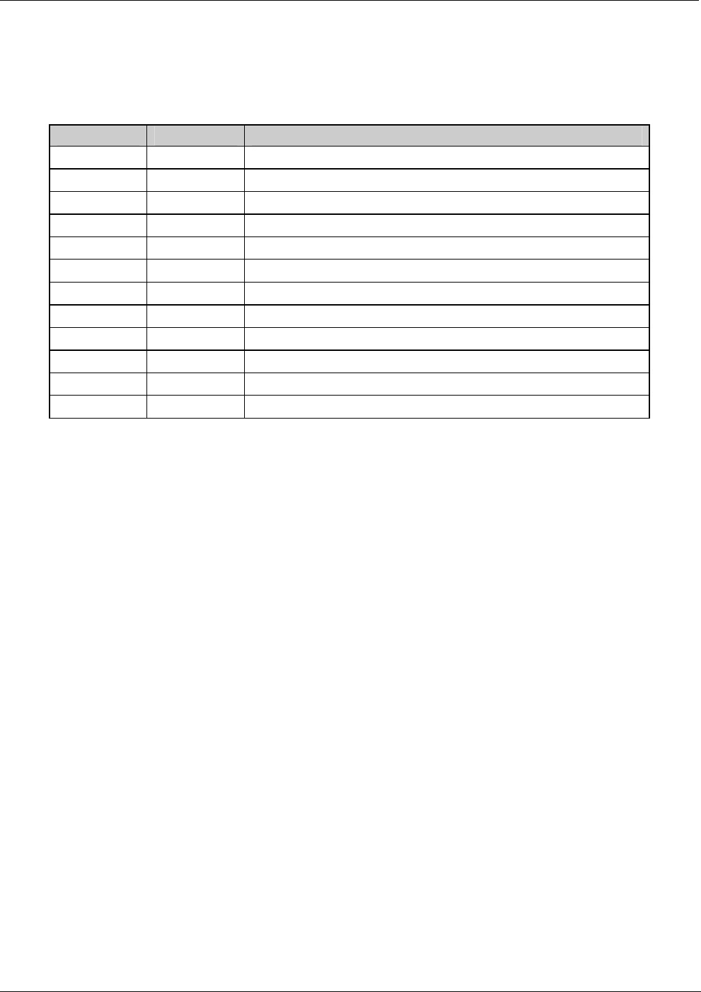
Table 11-11: T703 Control Input Pin Assignments and Corresponding Signal I/O Functions
CONNECTOR INPUT CORRESPONDING I/O SIGNAL
Top A
CONTROL_IN_1
Top B
CONTROL_IN_2
Top C
CONTROL_IN_3
Top D
CONTROL_IN_4
Top E
CONTROL_IN_5
Top F
CONTROL_IN_6
Bottom G
CONTROL_IN_7
Bottom H
CONTROL_IN_8
Bottom I
CONTROL_IN_9
Bottom J
CONTROL_IN_10
Bottom K
CONTROL_IN_11
Bottom L
CONTROL_IN_12
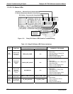
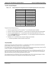
The control input bits can be tested by applying a trigger voltage to an input and watching changes in the status
of the associated function under the SIGNAL I/O submenu:
EXAMPLE: to test the “A” control input:
1. Under the DIAG SIGNAL I/O menu (See Section11.1.3), scroll through the inputs and outputs until
you get to the output name
d
0) CONTROL_IN_1.
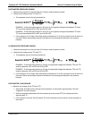
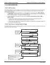
2. Connect a jumper from the
“+” pin on the appropriate connector to the “U” on the same connector.
3. Connect a second jumper from the “” pin on the connector to the “A” pin.
4. The status of 0) CONTROL_IN_1 should change to read “ON”.
07223B DCN6378