


Teledyne API T703 Calibrator Operation Manual Theory of Operation
161
RELAY PCA
SENSOR SUITES
LOGIC DEVICES
(e.g. CPU, I
2
C bus,
Motherboard, etc.)
ON / OFF
SWITCH
PS 2
(+12 VDC)
Photometer
M/R valve
Cooling
Fan
PS 1
ANALOG SENSORS
O
3
Generator
Reference detector,
Photometer UV
Detector
Pre-Amplifiers
& Amplifiers
Sensor Control
& I/O Logic
Solenoid
Drivers
KEY
AC POWER
DC POWER
AC
POWER IN
+5 VDC
±15 VDC
O
3
Generator UV
Lamp Xfromer
Photometer
UV Lamp P/S
GAS
PRESSURE
SENSORS
GAS
TEMPERATURE
SENSORS
O
3
Generator UV
Lamp P/S
O
3
Generator
UV Lamp
Photometer
Pump
Controlled
via I
2
C
DRY AIR
Pump
AC
Relay
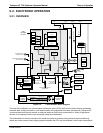
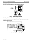
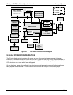
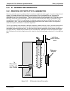
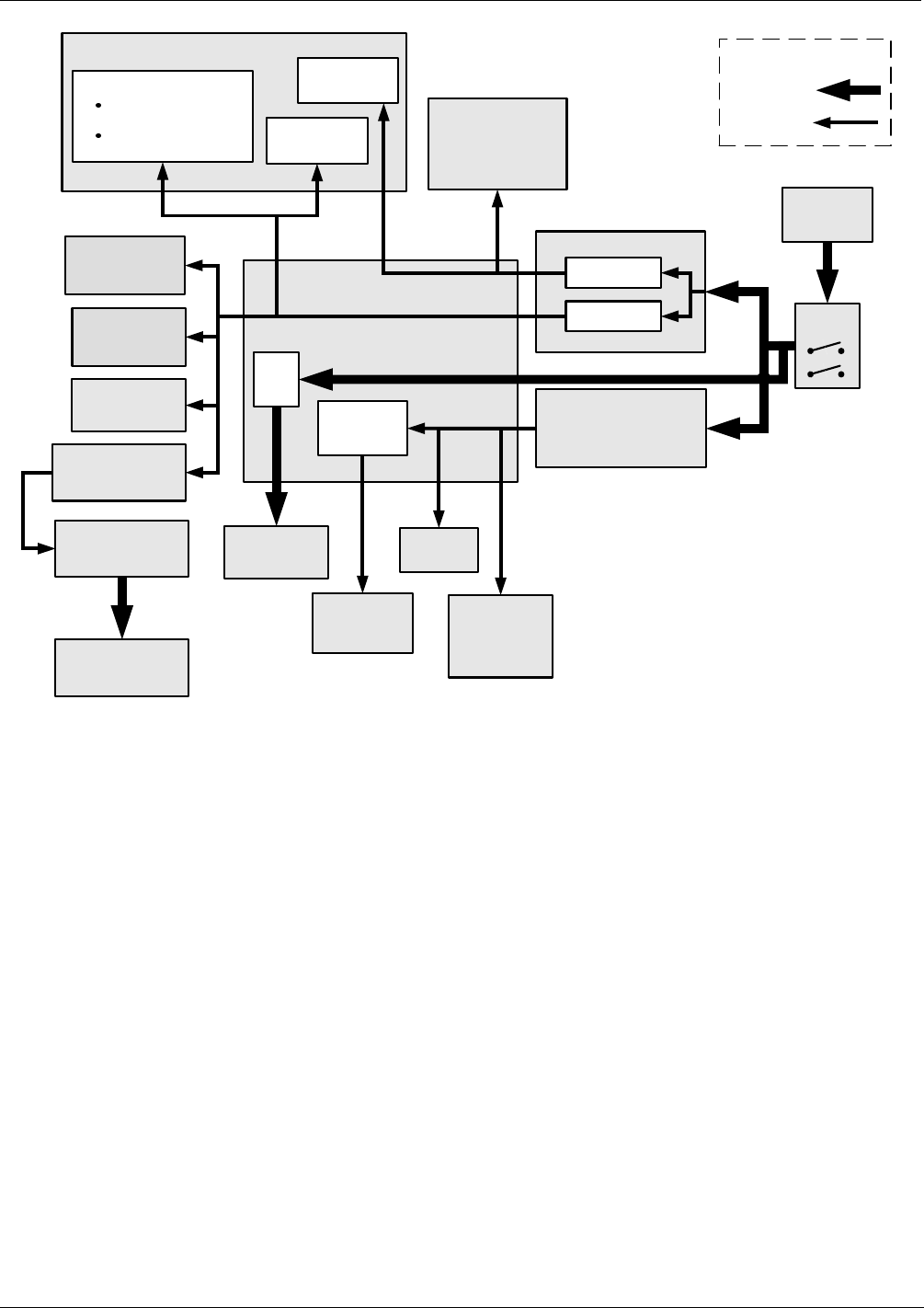
Figure 9-7: T703 Power Distribution Block diagram
9.2.6. AC POWER CONFIGURATION
The E-Series digital electronic systems will operate with any of the specified power regimes. As long as
instrument is connected to 100-120 VAC or 220-240 VAC at either 50 or 60 Hz it will turn on and after about 30
seconds show a front panel display. Internally, the status LEDs located on the Relay PCA, Motherboard and
CPU should turn on as soon as the power is supplied.
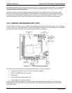
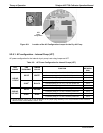
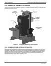
On the other hand, some of the calibrator’s the dry air pump must be properly configured for the type of power
being supplied to the instrument. Figure 2-3 shows the location of the Pump AC Configuration jumper.
07223B DCN6378