Teledyne API T703 Calibrator Operation Manual Table of Contents
xi
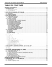
7.1.7.1. Help Commands in Terminal Mode............................................................................................. 112
7.1.7.2. Command Syntax........................................................................................................................ 113
7.1.7.3. Data Types .................................................................................................................................. 113
7.1.7.4. Status Reporting.......................................................................................................................... 114
7.1.7.5. COM Port Password Security...................................................................................................... 115
7.2. Remote Access by Modem....................................................................................................................... 116
7.3. Multidrop RS-232 Set Up.......................................................................................................................... 118
7.4. RS-485 Configuration of COM2................................................................................................................ 120
7.5. Remote Access via the Ethernet............................................................................................................... 120
7.5.1. Configuring the Ethernet Interface using DHCP................................................................................. 121
7.5.1.1. Manually Configuring the Network IP Addresses........................................................................ 123
7.5.2. Changing the Calibrator’s Hostname.................................................................................................. 125
7.6. APICOM Remote Control Program........................................................................................................... 126
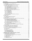
8. T703 CALIBRATION AND VERIFICATION ..................................................................... 129
8.1. Verifying and Calibrating the T703’s O
3
Photometer................................................................................ 129
8.1.1. Setup for Verifying and calibrating the O
3
Photometer....................................................................... 129
8.1.1.1. Calibration Manifold Exhaust/Vent Line ...................................................................................... 130
8.1.2. Verifying O
3
Photometer Performance ............................................................................................... 131
8.1.3. Calibrating the O
3
Photometer............................................................................................................ 132
8.1.3.1. Photometer Zero Calibration ....................................................................................................... 132
8.1.3.2. Photometer Span Calibration ...................................................................................................... 133
8.1.4. O
3
Photometer Dark Calibration ......................................................................................................... 134
8.1.5. O
3
Photometer Backpressure Calibration........................................................................................... 135
8.2. Calibrating the O
3
Generator .................................................................................................................... 136
8.2.1. O
3
Generator Calibration table............................................................................................................ 136
8.2.2. Viewing O
3
Generator Calibration Points............................................................................................ 137
8.2.3. Adding or Editing O
3
Generator Calibration Points............................................................................. 138
8.2.4. Deleting O
3
Generator Calibration Points........................................................................................... 139
8.2.5. Turning O
3
Generator Calibration Points ON / OFF ........................................................................... 140
8.2.6. Performing an Automatic Calibration of the O
3
Generator ................................................................. 141
8.3. T703 Gas Pressure Sensor Calibration .................................................................................................... 142
8.3.1.1. Gas Pressure Sensor Calibration Set Up.................................................................................... 142
8.3.2. Calibrating the Regulator and Photometer Pressure Sensors ........................................................... 144
8.4. T703 Gas Flow Calibration ....................................................................................................................... 145
8.4.1. Calibrating the Photometer’s Sample Gas Flow................................................................................. 146
8.4.2. Calibrating the Output Gas Flow......................................................................................................... 147
8.4.2.1. Output Gas Flow Set Up ............................................................................................................. 147
8.4.2.2. Performing an Output Gas Flow Calibration ............................................................................... 148
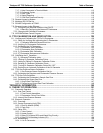
TECHNICAL INFORMATION................................................................................................ 149
9.
THEORY OF OPERATION............................................................................................... 151
9.1. Pneumatic Operation ................................................................................................................................ 151
9.1.1. Gas Flow Control ................................................................................................................................ 151
9.1.1.1. Flow Control Assemblies............................................................................................................. 151
9.1.1.2. Photometer Critical Flow Orifice.................................................................................................. 151
9.1.2. Internal Gas Pressure Sensors........................................................................................................... 152
9.2. Electronic Operation ................................................................................................................................. 153
9.2.1. Overview............................................................................................................................................. 153
9.2.2. Central Processing Unit (CPU)........................................................................................................... 154
9.2.2.1. Disk On Module (DOM)............................................................................................................... 155
9.2.2.2. Flash Chip ................................................................................................................................... 155
9.2.3. Relay PCA .......................................................................................................................................... 155
9.2.3.1. Valve Control............................................................................................................................... 156
9.2.3.2. Heater Control ............................................................................................................................. 157
9.2.3.3. Relay PCA Status LEDs and Watch Dog Circuitry...................................................................... 157
9.2.3.4. Relay PCA Watchdog Indicator (D1)........................................................................................... 158
9.2.4. Motherboard........................................................................................................................................ 159
9.2.4.1. A to D Conversion ....................................................................................................................... 159
07223B DCN6378


