


Teledyne API T703 Calibrator Operation Manual Operating The T703 over the Serial I/O Ports
119
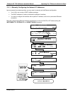
Note: If you are adding an instrument to the end of a previously configured chain, remove the shunt
between Pins 21 22 of the Multidrop PCA in the instrument that was previously the last instrument in
the chain.
3. Close the instrument.
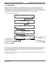
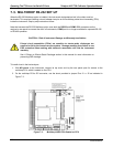
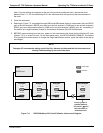
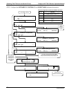
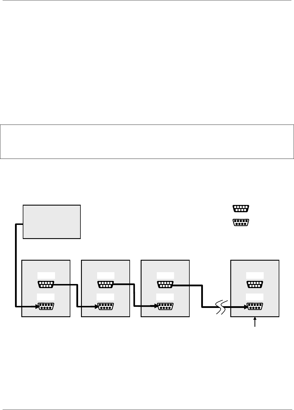
4. Referring to Figure 7-4, use straight-through DB9 male-DB9 fema
le cables to interconnect the host RS232
port to the first analyzer’s RS232 port; then from the first analyzer’s COM2 port to the second analyzer’s
RS232 port; from the second analyzer’s COM2 port to the third analyzer’s RS232 port, etc., connecting in
this fashion up to eight analyzers, subject to the distance limitations of the RS-232 standard.
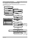
5. BEFORE communicating from the host, power on the instruments and check that the Machine ID code
(Section 7.5.2) is unique for each. On the front pane
l menu, use SETUP>M
ORE>COMM>ID. The default
ID is typically the model number; to change the 4-digit identification number, press the button of the digit to
be changed.
NOTE:
Teledyne API recommends setting up the first link, between the Host and the first instrument and
testing it before setting up the rest of the chain.
Analyzer Analyzer Analyzer Last Analyzer
Female DB9
Male DB9
RS-232
COM2
RS-232
COM2
RS-232
COM2
RS-232
COM2
Host
RS-232 port
Ensure jumper is
installed between
JP2 pins 21
22 in
last instrument of
multidrop chain.
Figure 7-4: RS232-Multidrop PCA Host
/Calibrator Interconnect Diagram
07223B DCN6378