


Maintenance Schedule & Procedures Teledyne API T703 Calibrator Operation Manual
182
Do not re-apply vacuum as it will draw soap solution into the instrument and contaminate it.
Do not exceed 15 psi pressure.
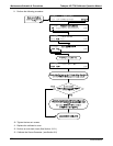
11. Once the leak has been located and repaired, the leak-down rate should be < 1 in-Hg (0.4 psi) in 5
minutes after the pressure is shut off.
O
3
FLOW
SENSOR
O
3
Generator Assembly
O
3
GENERATOR
Flow Control
(100 cm
3
/min)
Flow Control
(5.0 lpm)
Flow Control
(1.0 to 2.0 LPM)
CHARCOAL
SCRUBBER
CAP
CAP CAP CAP
CAP
CAP
UNION
UNION
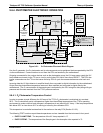
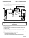
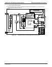
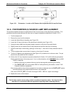
Figure 10-1: Pneumatic setup for performing Pressure Leak Checks
NOTE
The T703 calibrator cannot be leak checked with the pump in line due to internal leakage that normally
occurs in the pump.
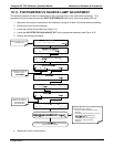
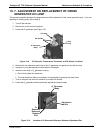
1. Remove the instrument cover
2. Locate the photometer pump.
3. Disconnect the two fittings on the photometer pump and install a union fitting in place of the pump.
4. Locate the dry air pump.
5. Disconnect the two fittings on the dry air pump and install a union fitting in place of the pump.
6. Locate the photometer pump.
7. Disconnect the two fittings on the photometer pump and install a union fitting in place of the pump.
8. Pressurize the instrument with the leak checker, allowing enough time to pressurize the instrument fully.
9. Check each fitting with soap bubble solution, looking for bubbles.
Once the fittings have been wetted with soap solution.
Do not re-apply vacuum as it will draw soap solution into the instrument and contaminate it.
07223B DCN6378