


T703 Calibration and Verification Teledyne API T703 Calibrator Operation Manual
146
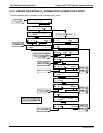
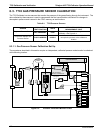
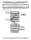
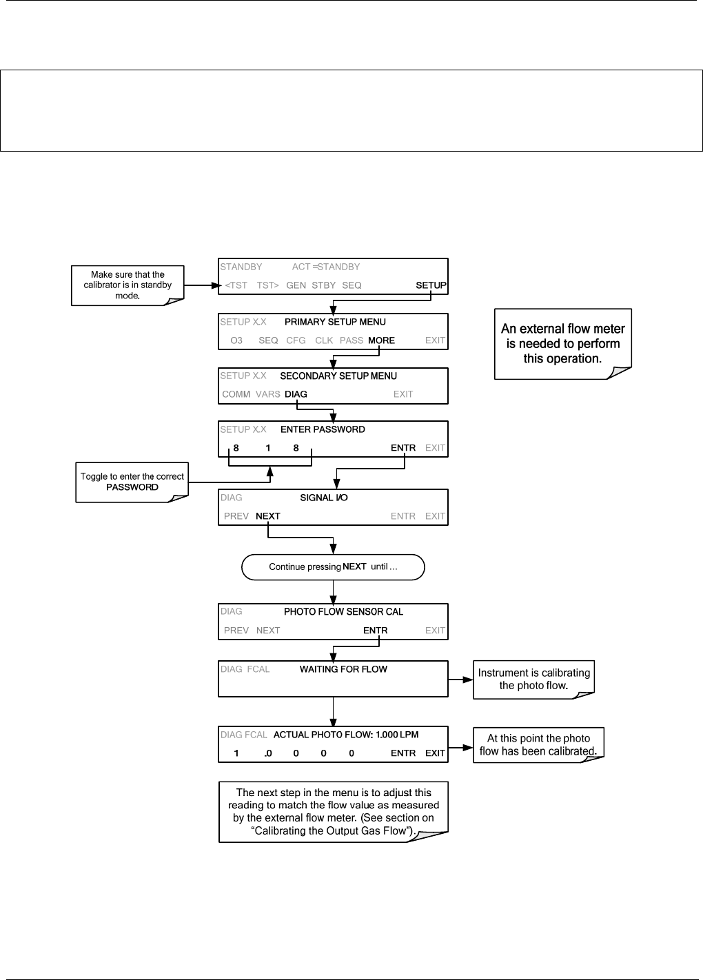
8.4.1. CALIBRATING THE PHOTOMETER’S SAMPLE GAS FLOW
NOTE
The procedure described in this section requires an independent, calibrated gas flow meter/monitor be
connected to the EXHAUST fitting on the back of the T703.
During the PHOTO FLOW calibration, the T703 software automatically turns the DC pump downstream from the
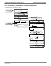
photometer ON. PHOTO FLOW calibration is followed by ACTUAL OUTPUT FLOW (output gas flow) calibration
(Section 8.4.2).
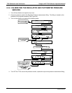
To perfo
rm a
PHOTO FLOW calibration, press:
07223B DCN6378