


Teledyne API T703 Calibrator Operation Manual Theory of Operation
171
5 – 6 Seconds
Analyzer measures the average UV light intensity of Non-O
3
bearing Sample Gas (I
0
)
during this period
.
CYCLE REPEAT EVERY 6 SECONDS
PHOTOMETER
PRESSURE SENSOR
O
3
GEN / PHOTOMETER
PRESSURE / FLOW SENSOR PCA
O
3
GAS INPUT
PRESSURE SENSOR
O
3
FLOW
SENSOR
O
3
Generator Assembly
O
3
GENERATOR
Flow Control
(1.0 LPM)
REF/MEAS
Valve
On Back Panel
Chassis
GAS OUTPUT MANIFOLD
PHOTOMETER
OUTLET
TO ANALYZER
VENT
TO ANALYZER
PHOTOMETER
INLET
EXHAUST
PHOTOMETER
ZERO OUT
PHOTOMETER
ZERO IN
PHOTOMETER BENCH
PUMP
INTERNAL
VENT
Flow Control
(5.0 lpm)
Pressure
Regulator
Filter
DRY AIR
IN
ZERO AIR
IN
PUMP
CHARCOAL
SCRUBBER
blk
blk
blu
blu
orn
orn
orn
orn
red
red
pur
pur
grn
grn
yel
yel
Flow Control
(100 cm
3
/min)
Flow Control
(800 cm
3
/min)
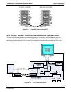
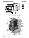
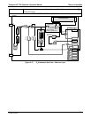
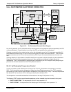
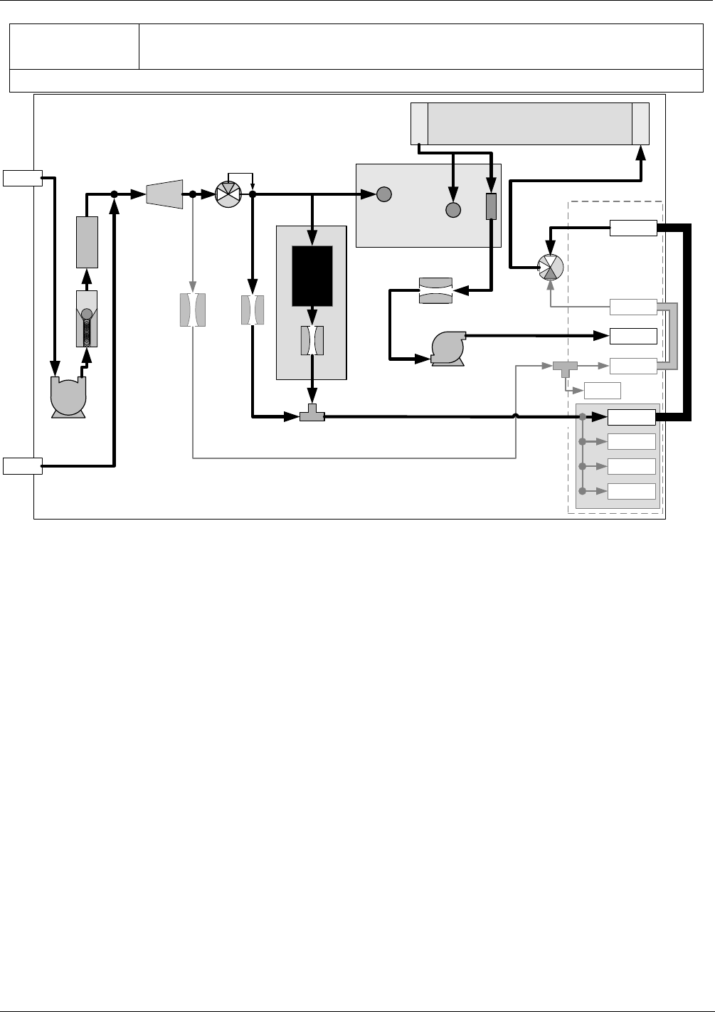
Figure 9-17: O
3
Photometer Gas Flow – Measure Cycle
07223B DCN6378