


Getting Started Teledyne API T703 Calibrator Operation Manual
36
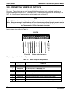
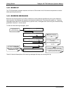
3.2.6. COMMUNICATION CONNECTIONS
The T-Series analyzers are equipped with connectors for remote communications interfaces. This section
describes those features.
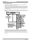
3.2.6.1. Ethernet Connection
For network or Internet communication with the analyzer, connect an Ethernet cable from the analyzer’s rear
panel Ethernet interface connector to an Ethernet port.
The T703 firmware supports dynamic IP addressing or DHCP (default setup) for remote operation via an
Ethernet connection. If your network also supports DHCP, the calibrator will automatically configure its LAN
connection appropriately (see Section 7.5.1). If your network does not supp
ort
DHCP, see Section 7.5.1.1 for
instructions on manually configuring the LAN connection.
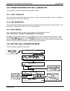
3.2.6.2. USB Option Connection
For direct communication between the analyzer and a personal computer (PC), connect a USB cable between
the analyzer and desktop or laptop USB ports. (If this option is installed, the COM2 port can only be used for
RS232 multidrop communication). The baud rate of the PC and the analyzer must match. See Section 7.1.3.
3.2.6.3. RS-232 and RS485 Connection
For RS-232 communications through the serial interface COMM ports, refer to Section 7.1.1 of this manual for
instructions on configuration and usage. For RS-485 communication, contact the factory.
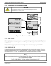
3.2.6.4. Multidrop Network Connection
If your unit has a Teledyne API RS-232 multidrop card (Option 62), see Section 7.3 for instructions on setting it
up.
07223B DCN6378