


General Troubleshooting & Repair Teledyne API T703 Calibrator Operation Manual
200
11.4.3. DC POWER SUPPLY
If you have determined that the calibrator’s AC mains power is working, but the unit is still not operating properly,
there may be a problem with one of the instrument’s switching power supplies. The supplies can have two
faults, namely no DC output, and noisy output.
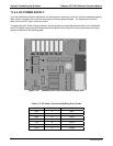
To assist tracing DC Power Supply problems, the wiring used to connect the various printed circuit assemblies
and DC Powered components and the associated test points on the relay PCA follow a standard color-coding
scheme as defined in the following table.
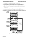
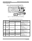
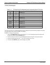
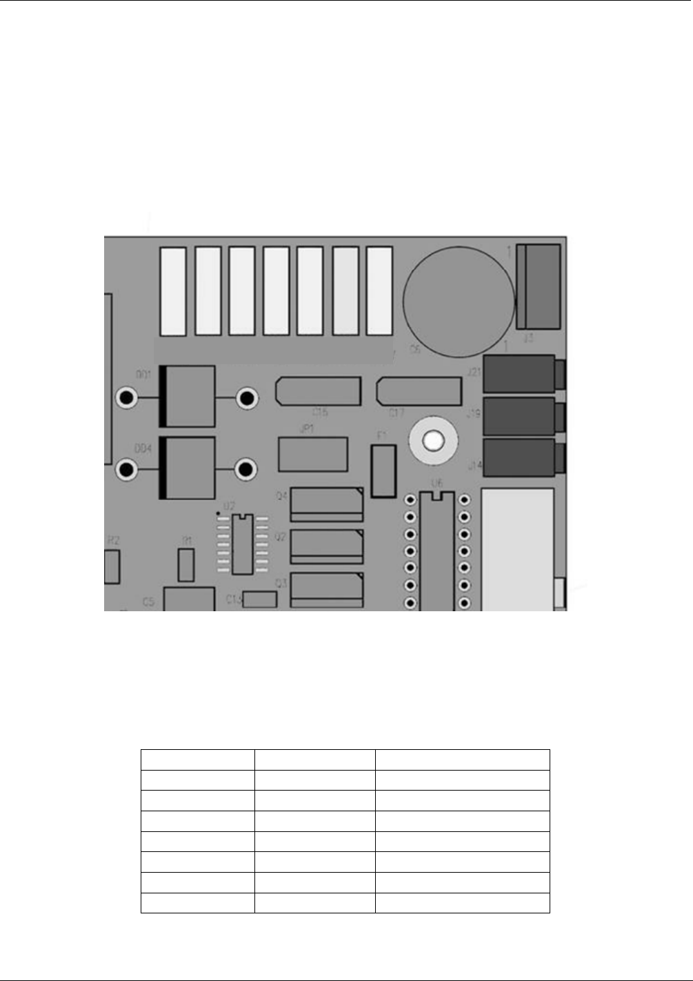
TP1 TP2 TP3 TP4 TP5 TP6 TP7
DGND +5V AGND +15V -15V +12R 12V
Figure 11-4: Location of DC Power Test Points on Relay PCA
Table 11-6: DC Power Test Point and Wiring Color Codes
NAME TEST POINT# TP AND WIRE COLOR
Dgnd
1
Black
+5V
2
Red
Agnd
3
Green
+15V
4
Blue
-15V
5
Yellow
+12R
6
Purple
+12V
7
Orange
07223B DCN6378