


Theory of Operation Teledyne API T703 Calibrator Operation Manual
156
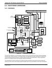
Power
Connections
for DC
Heaters
Status LED’s
(D2 through D16)
DC Power Supply
Test Points
Watchdog
Status LED (D1)
I
2
C Connector
DC
Valve Control
Drivers
AC Power
IN
DC Power
Distribution
Connectors
DC
V
alve &
Photometer
Pump Control
Connector
A
C Power
OUT to Dry
Air Pump
AC Pump
Configuration
Plug
Dry Air AC Pump
Control Relay
DC Valve &
Photometer
Pump
Control
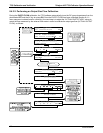
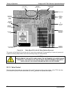
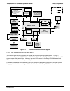
Figure 9-4: Relay Board PCA with AC Relay Retainer Removed
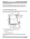
This version of the Relay PCA includes one AC relay that controls the AC-powered Dry Air (zero air) pump and
A plastic insulating safety shield covers the remaining empty AC Relay sockets.
CAUTION
NEVER REMOVE THIS SAFETY SHIELD WHILE THE INSTRUMENT IS PLUGGED IN AND
TURNED ON. THE CONTACTS OF THE AC RELAY SOCKETS BENEATH THE SHIELD
CARRY HIGH AC VOLTAGES EVEN WHEN NO RELAYS ARE PRESENT
9.2.3.1. Valve Control
The relay board also hosts two valve driver IC's, each of which can drive up four valves. In the T703, the relay
PCA controls only those valves associated with the O
3
generator and photometer options.
07223B DCN6378