Assembly\Disassembly 5-2
NovaJet 800 Series Service Manual
A Hardware Kit is available for the printers. See Chapter 6 of this
manual for the part number.
WARNING
Always turn the printer OFF, remove the power cord and
the interface cable before beginning any disassembly pro-
cedures. An electrical shock hazard may be present if
these precautions are not followed.
Remove the Left, Top, and Right Covers
Removing the Left Cover allows access to the left side of the Platen for
removal of the Carriage Assembly, Carriage Drive Belt, Tension Assem-
bly, and the Cutter Activator. Also located on this side is the ink reservoirs
and the Ink Delivery System portion that is connected to the reservoirs.
Removal of the Left Cover is a requirement to remove the Lower Roller
Assembly and the Vacuum Fan(s) from inside the Platen.
Removing the Right Cover provides access to the Main Printed Wiring
Assembly (PWA), Display and Keypad circuits, Servo Motor, AC Entry
Module, Power Supply and the Power Supply Cooling Fan.
The Top Cover needs to be removed before any of the other covers can
be removed. It also gives access to the Carriage Assembly and the
Service Station when in the open (up) position and the Carriage is at the
Carriage Access position.
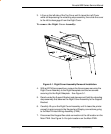
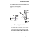
To remove the Top Cover:
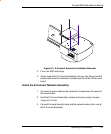
1. Put the Top Cover in the open position by lifting the front of the Cover
to the full upward position.
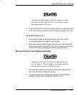
2. Depress and hold the retracting stop assembly located on the left side
of the Top Cover to disengage it from the Left Cover.


