


NovaJet 800 Series Service Manual
Assembly\Disassembly 5-15
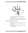
8. Connect the Vacuum Fan 1 connector to J15 on the Main PWA.
9. Connect the AutoLoad Sensor connector to J13 on the Main PWA.
10. Connect and lock the Trailing Cable A connector to J1 on the Main
PWA.
11. Connect and lock the Trailing Cable B connector to J2 on the Main
PWA.
12. Connect the Leg Harness connector to J6 on the Main PWA.
13. Connect the Servo Motor connector to J12 on the Main PWA.
14. Connect the Stepper Motor connector to J7 on the Main PWA.
15. Connect the Power Supply connector to J8 on the Main PWA.
16. Reinstall the Memory Module into U24 by following procedures
outlined earlier in this chapter.
17. Install the Top and Right Covers following procedures outlined earlier
in this chapter.
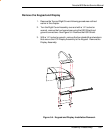
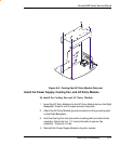
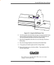
Remove Power Supply, Cooling Fan, and AC Entry Module
1. Remove the Top and Right Covers and the Main PWA following
procedures outlined earlier in this chapter.
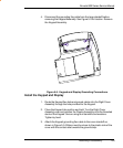
2. Ensure that the Main PWA is placed in an ESD bag (antistatic bag)
for protection.
3. Reach between the Power Supply Bracket and the AC Entry Module
and carefully pull out the quick disconnect assembly attaching the
Power Supply input to the AC Entry Module. Disconnect the Power
Supply input from the AC Entry Module.
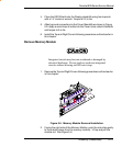
4. Disconnect the clip securing the power supply wires to the top of the
support bracket.
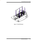
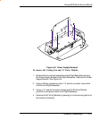
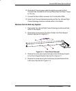
5. While holding the Power Supply in place, remove the four screws
securing it to the Power Supply Bracket. See Figure 5-8.
6. Slide the Power Supply out of the Power Supply Bracket.