Theory of Operation 2-12
NovaJet 800 Series Service Manual
commands which the Stepper Motor receives from the microprocessor.
The Stepper Motor Controller contains two identical circuits, one for each winding of the
stepper motor. The circuit is a combination of two simpler types of circuits and can be
thought of as a variation of either one.
A waveform generator receives digital data from the gate array and generates a sine
wave output. This signal is fed into a comparator circuit that is measuring the current
through the winding of the stepper motor. If the current is too low, a pulse of 24V is
generated. When the current goes above the output of the waveform generator, the pulse
turns off. Every time the output of the waveform generator is changed by the micropro-
cessor, the motor moves 1 “micro-step”.
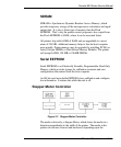
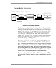
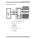
Each circuit contains four main functions (see Figure 2-7):
1. Reference waveform generator - the gate array uses a D/A (digital to analog)
converter to set the desired level for the current in the stepper motor winding. The
output of the D/A converter varies in time to create a reference waveform. This
reference waveform is centered around 2.5V.
2. Motor current sense - the voltage across a series current sense resistor is mea-
sured and level shifted so that it is centered around 5V.
3. Comparator - this portion divides the output of the reference waveform generator
by two and compares it to the output of the motor current sensor. Logic inside the
gate array generates the control signals for the power driver that applies voltage
across the motor winding in order to make the actual current match the reference
waveform.
4. Power driver - an H-bridge allows the supply voltage to be applied across the
winding in either polarity used to drive the current level to the desired value.


