


Theory of Operation 2-13
NovaJet 800 Series Service Manual
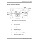
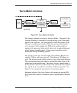
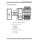
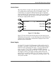
Servo Motor Controller
GATE
ARRAY
MOTOR
DRIVER
SERVO
CONNECTOR
CARRIAGE
CONNECTOR
SERVO
MOTOR
CARRIAGE
ENCODER
MAIN PWA
Figure 2-8. Servo Motor Controller.
The Carriage Assembly is driven by the Servo Motor. The speed of the
Carriage Assembly is controlled by varying the duty cycle of the signal
applied to the controller. The microprocessor checks the position of the
Carriage Assembly approximately 1,000 times per second (during the
servo interrupt). It then updates the PWM (pulse width modulator)
register in the gate array which sets the duty cycle to make adjustments
to the Carriage Assembly speed. A linear optical encoder is used to
monitor the Carriage Assembly position.
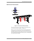
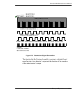
The optical encoder strip runs the length of the Stabilizer Bracket and
contains 150 lines and spaces per inch. Thus there are 300 edges per
inch. The detector circuit actually consists of two optical edge detectors.
They are separated from each other by one half the width of one of the
optical lines on the encoder strip. This allows 4 evenly spaced pulses to
be developed for each line on the encoder strip. This is known as quadra-
ture signals. It gives an effective resolution of 600 lines per inch. See
Figure 2-9 for a graphical representation of quadrature signals.
Maximum velocity of the Servo Motor is 46.6 inches per second (IPS).
Servo Motor life is rated to 2.8 million cycles or approximately 2800 plot
hours.