Assembly\Disassembly 5-56
NovaJet 800 Series Service Manual
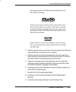
Disconnect the 2 carriage electronic covers by pressing in on the inner
tabs with a small tool. Disengage the trailing cables from the carriage
ZIF connectors. At rear of printer disengage each strain relief from
each carriage assembly using a small flat-head screwdriver – gently
pry the securing foot to one side to release the strain relief. Caution:
do not force strain relief or damage to carriage assembly may result.
23. Remove both carriage assemblies, belt, frame tensioner, idler, and
spring by sliding assemblies gently off the left side of the slide shaft.
Note: the carriage assemblies are connected together with a latch
and tension spring - ensure the orientation is correct for installation
(the right carriage assembly contains the sensor assemblies).
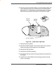
24. Remove the Y-Arm assembly by removing the 8 securing screws.
Caution: do not damage trailing cable or sensor wiring during removal.
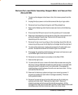
25. Remove the 2 middle platen section pin assembly compression
springs by removing the securing screw.
26. Remove 3 screws from right leg and twist 90 degrees to gain access
to screw holes.
27. Remove 4 screws securing the right fixed-platen end. Right stand leg
will have to be twisted to gain access to screw holes. Move platen
end away from stepper motor location and pull wiring free. Do not
disconnect leg harness wiring. Caution: do not loosen or remove any
main beam screws or improper printer alignment will result.
28. Remove the middle platen section by pulling straight up. Caution: do
not tamper with the media thickness hand wheel until the printer is
reassembled.
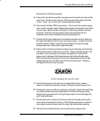
29. Remove the right side plate from the middle platen section by removing
the 4 securing screws. Disconnect both vacuum fans by removing the
6 securing screws. Remove the exhaust grills by removing the 8
securing screws and lifting grills free. Disconnect lower roller
assembly by removing the 6 securing screws. Remove the platen plug
by forcing a screwdriver past lower roller and pounding out forcefully.
Remove the center lower roller support bracket and bearing. Note:
The thick arm of the bracket faces towards the front of the printer on
reinstallation. Remove the stepper motor/lower roller assembly out the
right side of platen. Caution: do not pull lower roller too hard as this
may cause damage to the vacuum fans. The vacuum fans may have
to be lifted over the pemnuts when removing.


