


7
Chapter 7 Location and Function of Parts and Controls 100HDC-900/950/930 Series Product Information Manual
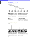
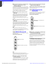
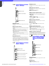
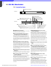
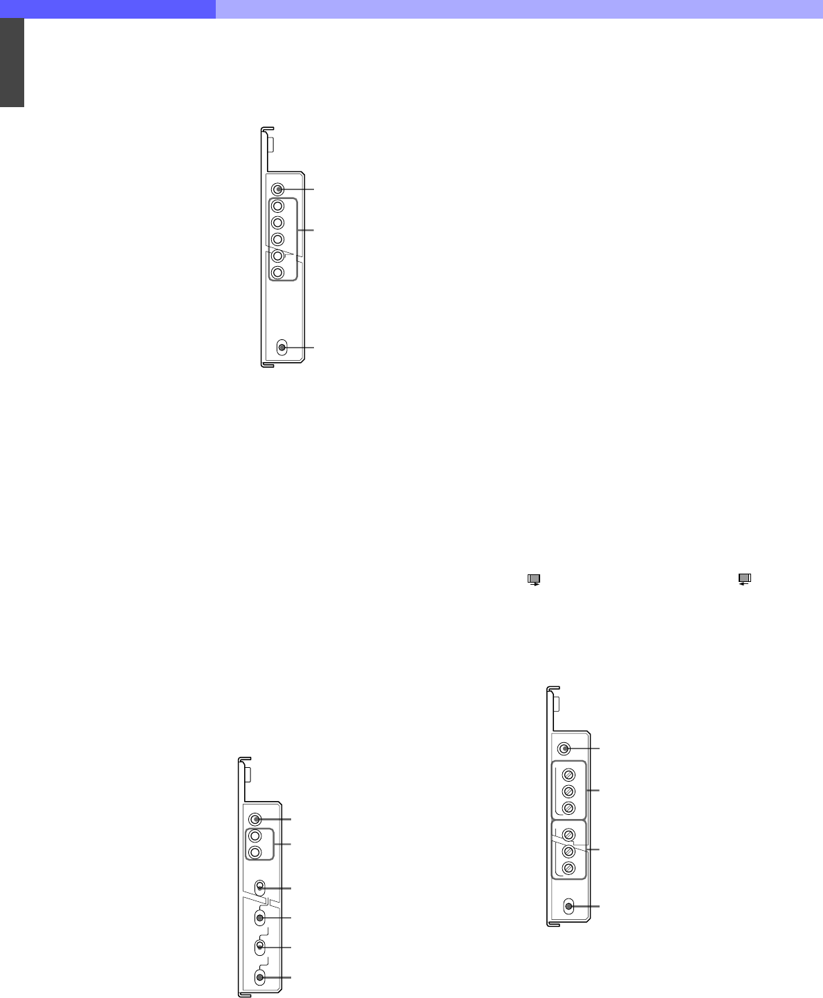
7-4-10 Internal Switches and Internal
Boards – DRX Board
a POWER indicator
The LED is lit when the power voltage inside the board
is normal.
b Camera status indicators
The LEDs will light to show the status of the connected
camera:
60/50/48: One of these LEDs that corresponds to the
field frequency setting on the camera lights.
PsF: The LED is lit when the camera is operating in
Progressive mode.
540P: The LED is lit when the camera is operating in
540-60P mode (not used at present).
Operation mode of the camera is set from the camera
control unit.
c CHARACTER switch
To page the character displays being imposed to the
monitor output. This switch will return to its original
position when you release it. Press it toward FF to go to
the next page or toward REW to return to the previous
page. When you hold the button pressed, the display
changes continuously.
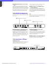
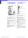
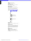
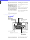
7-4-11 Internal Switches and Internal
Boards – RC Board
a POWER indicator
The LED is lit when the power voltage inside the board
is normal.
b SD signal format indicators
Either of the indicators lights to show the selected SD
signal format:
525: 525-59.94i (NTSC) format
625: 625-50i (PAL) format
c Down-converter remote/local switch
To specify whether the down converter is remotely set
or locally set.
REM (remote): To set from the MSU-700A/750 Master
Setup Unit
LOCAL: To set on this unit
The switches d, e, and f become valid with the
LOCAL setting.
d Down-converter mode switch
To select the operating mode of the down converter:
SQ: Squeeze mode
LB: Letterbox mode
EC: Edge-Crop mode
The switches e and f become valid with the EC
setting.
e Edge-crop mode setting switch
To set the Edge-crop mode of the down converter:
CENT: To fix the picture frame at the center when
performing edge crop
VAR: The edge crop position can be varied with the
edge-crop position-setting switch f.
f Edge-crop position setting switch
To set the edge crop position. This switch will return to
its original position when you release it. Press and hold
the switch toward RIGHT to move the position to the
right ( ) and toward LEFT to move it to the left ( ).
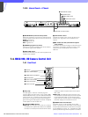
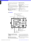
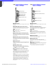
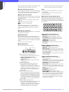
7-4-12 Internal Switches and Internal
Boards – EN Board (Internal
board of the optional HKCU-
951)
a POWER indicator
The LED is lit when the power voltage inside the board
is normal.
b VBS controls
To adjust VBS signal:
LEVEL: To adjust the video level
DRX
POWER
60
50
48
PsF
540P
CHARACTER
REW
FF
1 POWER indicator
2 Camera status indicators
3 CHARACTER switch
RC
POWER
525
625
RIGHT
LEFT
SQ
LB
EC
CENT
VAR
REM
LOCAL
1 POWER indicator
2 SD signal format indicators
3 Down-converter remote/local switch
4 Down-converter mode switch
5 Edge-crop mode setting switch
6 Edge-crop position setting switch
EN
POWER
LEVEL
SYNC
CHROMA
SC PHASE
COMPONENT
VBS
ADV
B/B-Y
G/Y
R/R-Y
DELAY
1 POWER indicator
2 VBS controls
3 COMPONENT controls
4 SC PHASE switch