


7
Chapter 7 Location and Function of Parts and Controls 98HDC-900/950/930 Series Product Information Manual
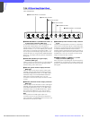
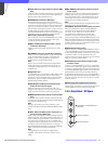
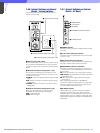
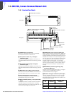
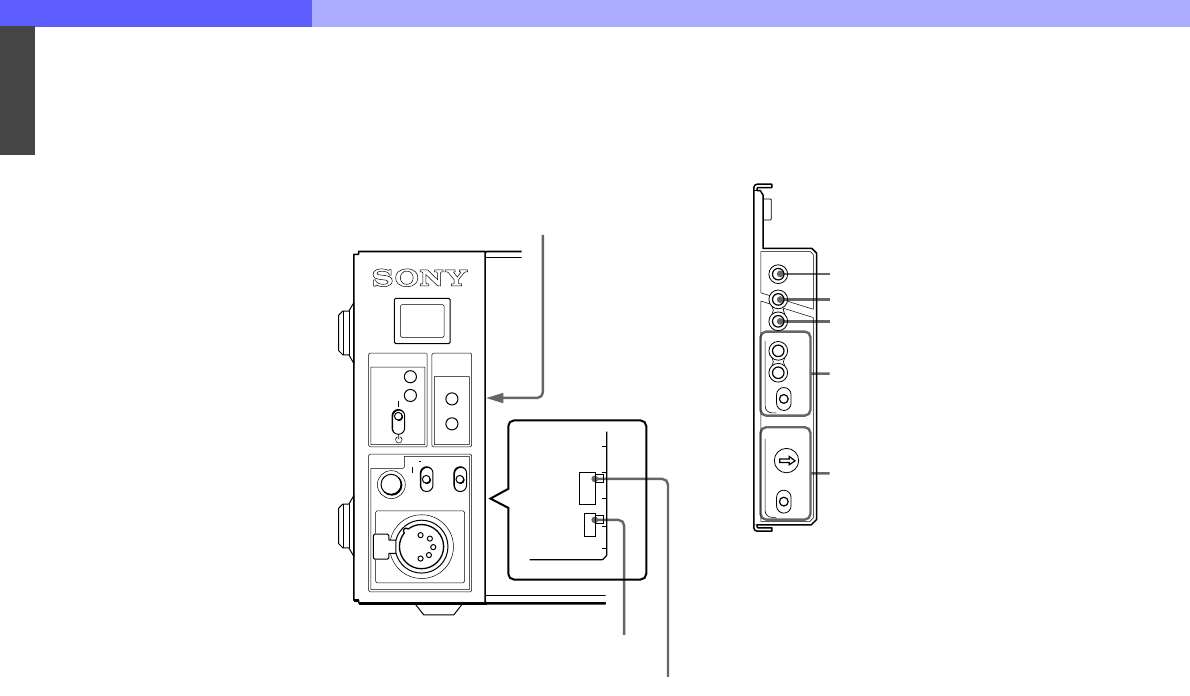
7-4-6 Internal Switches and Internal
Boards – Internal switches
The following switches are located inside the unit
behind the front panel:
a Internal main power switch
When an abnormality has occurred, and power cannot
be cut off with the POWER switch on the front panel,
you may turn off the unit using the internal main power
switch.
b Headset microphone setting switch 1 (S4)
Set the switch according to the microphone of the
headset connected to the intercom connector on the
front panel of this unit:
CARBON: Carbon microphone (power supply, 20- dB
gain)
ECM: Electret condenser microphone (power supply,
40-dB gain)
DYNAMIC: Dynamic microphone (no power supply,
60-dB gain)
c Headset microphone setting switch 2 (S5)
When you set setting switch 1 (S4) to ECM or
DYNAMIC, also set this switch accordingly:
GND: Unbalanced type
OPEN: Balanced type
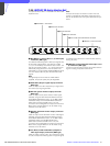
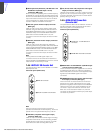
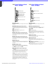
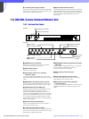
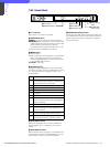
7-4-7 Internal Switches and Internal
Boards – AT Board
a POWER indicator
The LED is lit when the power voltage inside the board
is normal.
b /1.001 (frame frequency) indicator
The LED is lit when the frame frequency of the system
is set to 1/1.001.
c 90H (phase difference) indicator
The LED is lit when the phase difference between the
HD output and SD output is set to 90H (HD).
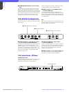
d REFERENCE indicators and switch
The switch is to select the type of sync signal to be
connected to either of the REFERENCE connectors on
the rear panel.
HD: HD tri-level reference sync signal (local setting)
REM (remote): Signal selected on the MSU-700A/ 750
Master Setup Unit
BB: SD reference sync signal (black burst signal)
(local setting)
When a signal is supplied to the REFERENCE
connector, the REF IN indicator lights. If the type of the
input sync signal does not match the setting on this
unit, the UNLOCK indicator will light.
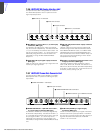
e H PHASE switches
Used to adjust the H phase. First set the phase by
steps with the STEP switch, then adjust it with the
COARSE switch. The COARSE switch will return to its
original position when you release it. Press and hold it
toward ADV to advance the phase or toward DELAY for
phase delay.
PROD
SHORT
OPEN
CAM
MAIN
CABLE
ALARM
INCOM
POWER
1
ENGPGM
ONMIC
OFF PRIV
S4
CARBON
ECM
DYNAMIC
GND
OPEN
S5
2 Headset microphone setting switch 2 (S5)
3 Headset microphone setting switch 1 (S4)
1 Internal main power switch
AT
POWER
/1.001
90H
REF IN
UN
LOCK
HD
REFERENCE
H PHASE
REM
BB
ADV
DELAY
STEP
COARSE
1 POWER indicator
2 /1.001 indicator
3 90H indicator
4 REFERENCE indicators and switch
5 H PHASE switches