


7
Chapter 7 Location and Function of Parts and Controls 84HDC-900/950/930 Series Product Information Manual
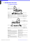
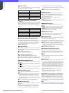
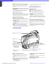
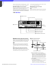
a TEST OUT (test output) connector (BNC type)
Connect to a monitor as necessary. The output will be
the signal selected with the Y/RGB and R/G/B/
switches.
b MIC 1 IN (microphone 1 input) connector (XLR 3-
pin, female)
Connect a microphone. This connector and the AUDIO
IN CH-1 connector on the back are alternately
activated with the MIC IN switch.
c RET 1 (return video 1) button
The return video 1 signal from the camera control unit
is monitored on the viewfinder screen while this button
is pressed. It is the same function as with the RET 1
buttons on the grip and right side.
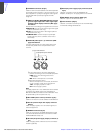
d MIC IN (microphone input) switch
Select either the microphone connected to the MIC 1
IN connector or that connected to the AUDIO IN CH-1
connector on the back.
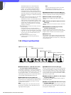
+48V/FRONT: To use the microphone connected to
the MIC1 IN connector and supply a power of +48 V
to the microphone.
OFF/FRONT: To use the microphone connected to the
MIC1 IN connector without supplying a power.
REAR: To use the microphone connected to the
AUDIO IN CH-1 connector on the back. Whether or
not to supply a power to the microphone can be set
with the exclusive microphone power switch of the
AUDIO IN CH-1 connector.
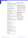
e VF (viewfinder) connector (20-pin)
Connect the viewfinder cable.
f SHUTTER switch1)
OFF: An electronic shutter does not function.
ON: An electronic shutter is activated.
SEL: The shutter speed and shutter mode change
each time the switch is set to this position.
g INCOM/EAR (intercom/earphone) LEVEL
control
To adjust the intercom/earphone volume level. The
intercom level adjustment is enabled when the INCOM
1/2 LEVEL switches on the right back panel are set to
“F.”
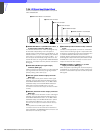
h VTR START (recording start/stop) button
When a VTR is connected, recording begins when this
button is pressed, and stops when it is pressed again.
This button functions the same as the VTR button on
the lens.
When a camera control unit is connected, the function
of this button can be changed to the RET2/INCOM1
MIC/INCOM2 MIC ON/OFF function on using the
OPERATION menu.
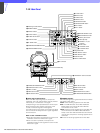
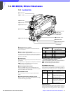
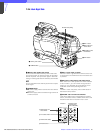
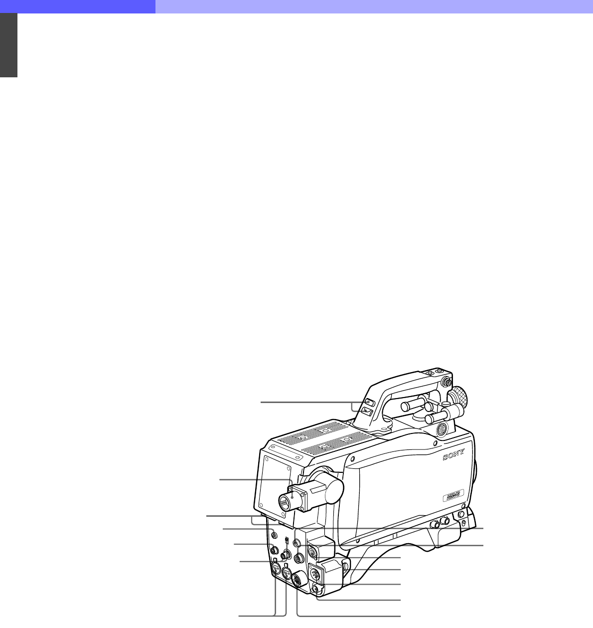
7-2-3 Back Left Side
a TALLY lamp and TALLY switch
ON: The tally lamp lights when a tally signal or a call
signal generated by pressing a CALL button is
received.
OFF: The tally lamp is prevented from lighting.
b CCU (Camera Control Unit) connector (optical
multi connector)
Connects to a camera control unit via an optical
electro-composite cable.
c INCOM1 and 2 (intercom 1 and 2) connectors
(XLR 5-pin)
Used for input and output of intercom audio signals.
d EARPHONE jack (minijack)
Connect an earphone or headset for output of the VTR
playback audio signal.
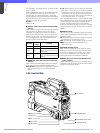
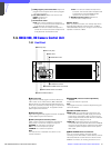
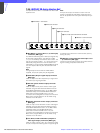
8 RET CONT
connector
1 TALLY lamp and TALLY switch
2 CCU connector
3 INCOM1 and 2
connectors
4 EARPHONE jack
5 TRACKER connector
6 GENLOCK IN/RET IN/
PROMPTER OUT
connector and switch
7 AUDIO IN connectors
and switches
qf VTR connector
qd HD SERIAL OUT connector
qs DC IN connector
qa DC OUT connector
q; REMOTE connector
9 EXT I/O connector