


7
Chapter 7 Location and Function of Parts and Controls 114HDC-900/950/930 Series Product Information Manual
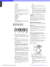
When one of these buttons is lit, pressing the
output signal select buttons has effect only on
the connector that corresponds to the lit
button. The output signal from the other
connector does not change. By lighting both
the buttons, you can simultaneously select the
output signal.
Note
If you light both the WF and PIX buttons when
different signals are selected for the WF2
OUTPUT and PIX2 OUTPUT connectors, the
output select buttons corresponding to the
signals selected for either of the connectors
flash. Press the button for the signal to be output
to select it again.
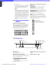
For example, when you light both the WF and
PIX buttons with R + B selected for PIX2
OUTPUT and B + G selected for WF2 OUTPUT,
the R and G buttons will start flashing, while the
B button will remain lit. To output R and G, press
the R and G buttons. Each pressed button stops
flashing and lights.
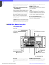
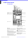
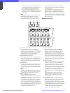
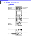
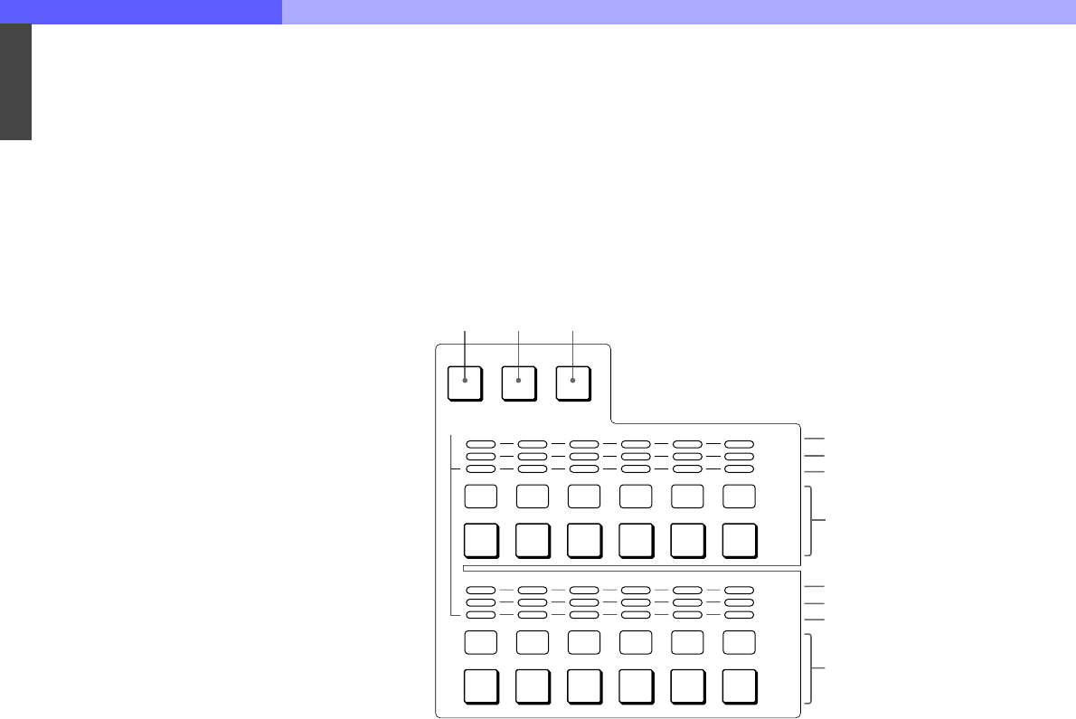
k Camera select block
A PANEL ACTIVE button
Press and light up this button to permit the
cameras selected with the camera select
buttons to be controlled from this unit. The IRIS/
MB ACTIVE button also lights up. If you press
the button when lit, it goes dark and the
operation panel of this unit is locked.
B PARA (parallel mode) button
Press and light up this button to activate Parallel
mode, which enables concurrent operation with
another control panel. If you press the button
when lit, it goes dark and the Parallel mode is
canceled.
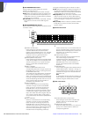
C EXPAND button
Press to select the group to be selected with the
camera select buttons. Cameras 1 through 12
can be selected when this button is not lit, and
cameras 13 through 24 can be selected when
this button is lit.
Note
An appropriate camera command network unit
(CNU- 700, etc.) is required to control multiple
cameras using the camera select function.
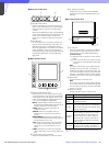
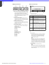
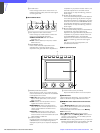
D MULTI indicators
Show the Master/Slave status of the
corresponding cameras 1 through 12 (when the
EXPAND button is not lit) or 13 through 24 (when
the EXPAND button is lit).
The indicator for the camera which is specified
as the master for Master/Slave mode lights in
green. The indicators for the slave cameras light
in orange. They light in red during the auto setup
of the corresponding cameras. If an error occurs
during the auto setup and the operation is
interrupted, they will flash in red.
E TALLY indicators
Show the tally status of the corresponding
cameras 1 through 12 (when the EXPAND
button is not lit) or 13 through 24 (when the
EXPAND button is lit). The corresponding
indicator lights in red when a red tally is sent to
a camera, and it lights in green when a green
tally is sent. When both red and green tally are
sent, it lights in orange. When a call signal is
sent to the camera, the indicator rapidly flashes
in red.
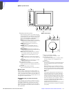
F Active indicators
Show the control status of the corresponding
cameras 1 through 12 (when the EXPAND
button is not lit) or 13 through 24 (when the
EXPAND button is lit). The indicators for the
cameras under control of this unit light in green
and the indicators for the cameras under control
of another control panel light in orange.
An indicator whose corresponding camera (or
camera control unit) is not connected does not
light.
An indicator lights in red when an error is
detected and the self-diagnostic functions are
activated in the corresponding camera or
camera control unit.
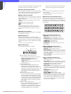
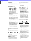
G Camera select buttons and camera number
indicators
Select the cameras to be controlled from this
unit. Press and light up the button
corresponding to each desired camera. When
the EXPAND button is not lit, numbers 1 through
12 are displayed and cameras 1 through 12 are
selected. When the EXPAND button is lit,
numbers 13 through 24 are displayed and
cameras 13 through 24 are selected.
0 7 0 8 0 9 1 0 1 1 1 2
0 1 0 2 0 3 0 4 0 5 0 6
PANEL
ACTIVE
PARA
EXPAND
MULTI
TALLY
MULTI
TALLY
4
5
6
7
4
5
6
7
123