


7
Chapter 7 Location and Function of Parts and Controls 79HDC-900/950/930 Series Product Information Manual
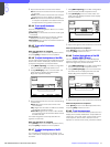
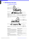
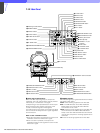
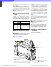
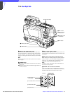
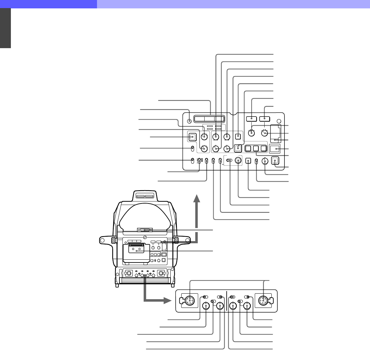
7-1-2 Rear Panel
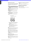
a Video signal select buttons
Select the video output signal (R, G, or B) to the
viewfinder. The R, G, and B buttons may be pressed
individually or in combination. The signal
corresponding to each pressed button will be output.
When two buttons are pressed, the output of will
consist of those two signals mixed together.
The video output to the monitor connected to the TEST
OUT connector will always be the Y signal regardless
of these buttons.
When a color viewfinder is used:
• When all three buttons are pressed, the output to the
viewfinder and monitor will be the Y signal.
• When no button is pressed, the output to the
viewfinder will be the color signals and to the monitor
will be the Y signal.
b POWER indicator
This indicator lights up or goes off as follows to indicate
the power supply status:
Green: Power is being supplied to the HDC-900.
Red: The CAM PW button of the MSU-700A/750
Master Setup Unit or RCP-700 series Remote
Control Panel is set to OFF.
Yellow: Power is being supplied to the HDC-900, but
the VF PW button of the MSU-700A/750 Master
Setup Unit or RCP-700 series Remote Control Panel
is set to OFF, and power is not being supplied to the
viewfinder.
Off: Power is not being supplied to the HDC-900.
qk CURSOR 1, 2, and
3 buttons
qj CALL button
qa DISPLAY switch
qs MENU SELECT switch
qd MENU SELECT control
qf Assignable switch
qg VF DETAIL switch
qh VF DETAIL control
1 Video signal select buttons
2 POWER indicator
3 ND filter selector
4 CC filter selector
5 FILTER LOCAL button
6 UP TALLY switch
7 VF SCAN switch
8 SCREEN SIZE MARKER switch
9 CENTER MARKER switch
q; SAFETY ZONE switch
e; H-POSI control
ea VF connector
wl WIDTH control
wk V-POSI control
wj HEIGHT control
wh CURSOR ON button
wg CURSOR STORE button
wf RET 2 button
wd RET 1 button
wa RETURN SELECT knob 1
ws RETURN SELECT knob 2
w; Memory stick section
ql Back tally lamp
es INTERCOM 1 and 2 connectors
ed INTERCOM PROD/ENG switch
ef INTERCOM volume control
1
1
POWER
RGB
RET 1
FILTER LOCAL
ND
2
3
4
1
2
3
4
1
5
CC
B
C
D
A
E
H-POSI V-POSI
WIDTH HEIGHT
STORE
CURSOR
VF DETAIL
123
ON
UP TALLY
ON
OFF
16:9
4:3
VF
SCAN
ON
OFF
SCREEN SIZE
MARKER
ON
OFF
CENTER
MARKER
ON
OFF
ON
OFF
SAFETY
ZONE
ON
MENU
DISPLAY
OFF
MENU SELECT
CANCEL ENTER
M
EMORY
S
TICK
CALL
ENG PROD
INTERCOM
OFF
12 12
ON
PGM
ENG PROD
INTERCOM
OFF ON
PGM
MIC MIC
INTERCOM 1 INTERCOM 2
RET 2
2
3
4
1
eg PGM 1/2 switch
eh PGM volume control
ej MIC ON/OFF switch
Memo clip
ed INTERCOM PROD/ENG switch
ef INTERCOM volume control
eg PGM 1/2 switch
eh PGM volume control
ej MIC ON/OFF switch