


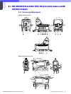
7
Chapter 7 Location and Function of Parts and Controls 138HDC-900/950/930 Series Product Information Manual
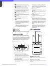
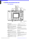
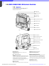
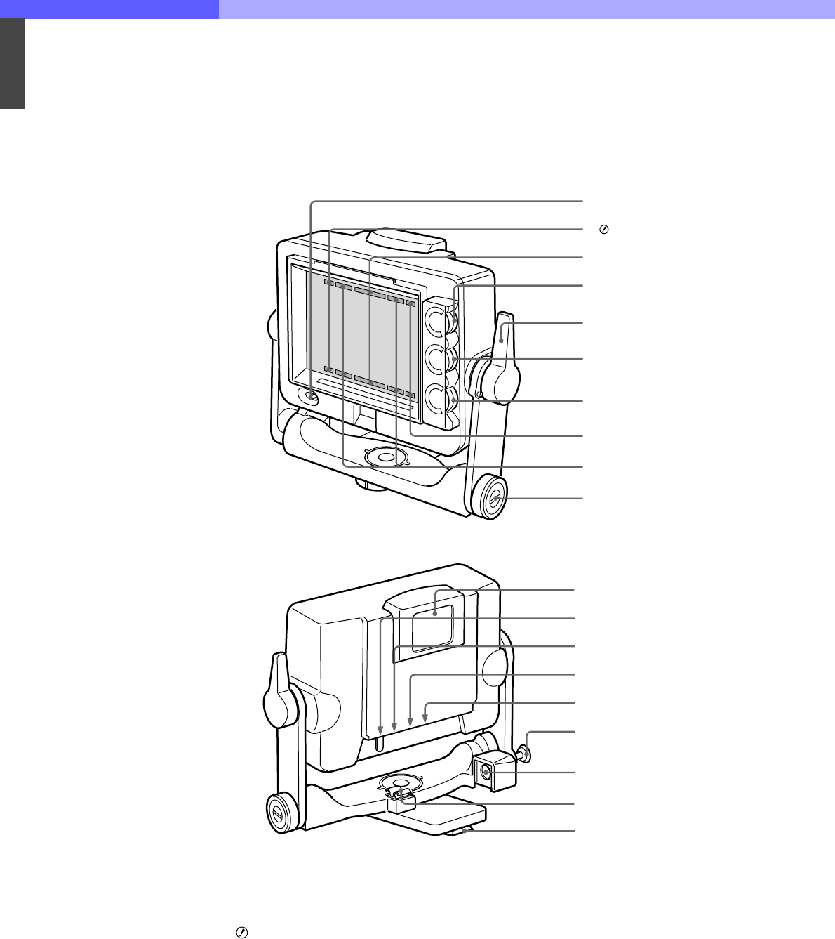
7-16. HDVF-C700W/C750W, HD Electronic Viewfinder
7-16-1 Appearance
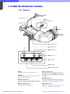
The figure illustrates the HDVF-C750W. The parts of
the HDVF-C750W and the HDVF-C700W have
basically the same functions.
a POWER switch
Turns the power supply from the camera to the
viewfinder on and off.
b (attention) indicator
This indicator lights when the camera detects certain
conditions. The particular conditions which cause the
indicator to light up are set up by the camera.
For information on how to set up and verify the
conditions under which the indicator will light, refer to
the manual for the camera being used.
c Red tally lamps
Light up when the camera receives a red tally signal.
d BRIGHT (brightness) control
*1
Adjusts the picture brightness.
e Friction adjustment/lock lever
Adjusts the amount of friction in the tilting mechanism.
Also, locks the viewfinder into a desired angle. The
angle is locked when the lever is pushed toward the
camera lens. When the lever is pulled toward the back
of the camera, the tilting mechanism can be adjusted.
f CONTRAST control
*1
Adjusts the picture contrast.
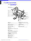
1 POWER switch
2 (attention) indicator
3 Red tally lamps
4 BRIGHT control
5 Friction adjustment/lock lever
6 CONTRAST control
7 PEAKING control
8 BATT indicator
9 Green tally lamps
q; Lift-lock release knob 1
Front
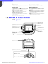
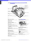
qa External tally lamp
qs External tally dimmer control
qd TALLY ON/OFF switch
qf Blanking marker ON/OFF switch
qg Tally dimmer switch
qh Lift-lock release knob 2
qj CAMERA connector
qk Clamper
ql Mounting wedge
Rear