


7
Chapter 7 Location and Function of Parts and Controls 77HDC-900/950/930 Series Product Information Manual
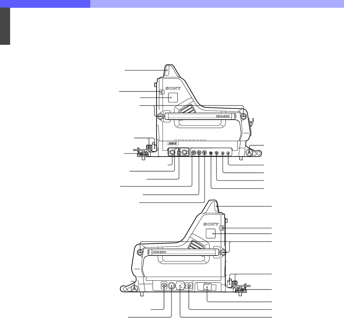
7-1. HDC-900, HD Color Video Camera
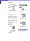
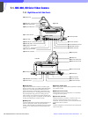
7-1-1 Right Side and Left Side Panels
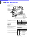
a Up tally lamp
Lights when the camera receives a red tally signal.
When the CALL button on the MSU-700A/750 Master
Setup Unit or the RCP-700 series Remote Control
Panel is pressed, the lamp lights if previously off or
goes off if previously on. The brightness of the lamp
may be adjusted using the menu. Setting the UP
TALLY switch on the rear panel to OFF will keep the
lamp from lighting. Attach a supplied number plate (0
through 9) to display the camera number.
b Safety lock
Locks the side panel to prevent accidental opening. To
open the side panel, loosen the side panel lock
screws, slide the safety lock toward the lens and open
the panel. The side panel locks automatically when
closed.
c Camera number plate
Attach a light gray number plate (supplied) to display
the camera number.
d Side panel lock screws
These screws secure the side panel. Turn clockwise
until tight to lock the panel.
e Lens lock and knob
These lock the lens. To attach or remove a lens, turn
the knob counterclockwise until the lens lock is
horizontal. To secure the lens, turn the knob clockwise
until the lens lock is vertical.
Note
To attach a large lens, remove the pin from the bayonet
mount of the lens.
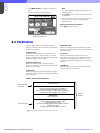
1
1
1 Up tally lamp
2 Safety lock
3 Camera number plate
4 Side panel lock screw
5 Lens lock and knob
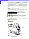
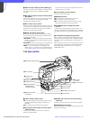
6 Cable clamp
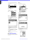
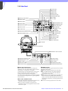
wa HD SERIAL OUT connector
w; VTR connector
7 Accessory bracket
5 Lens lock and knob
qf RET CONTROL connector
8 AUDIO IN CH-1 and CH-2 connectors
9 AUDIO IN switch
0 Microphone power switch
For feture use
qa PROMPTER connector
qs TEST OUT connector
ql AC OUT connector
qk DC IN connector
qj CCU connector
6 Cable clamp
4 Side panel lock screw
3 Camera number plate
2 Safety lock
1 Up tally lamp
qd REMOTE connector
qg TRACKER connector
qh DC OUT connector
7 Accessory bracket
Right side
Left side