


7
Chapter 7 Location and Function of Parts and Controls 95HDC-900/950/930 Series Product Information Manual
If the CAM PW button on the Remote Control Panel or
Master Setup Unit is pressed, only power to the
camera is turned off, and the CAM indicator alone
goes dark.
Note
Standby power is kept supplied even when the
POWER switch is set to off. The main power switch is
provided on the power unit behind the front cover. If
you open the front cover and set the main power switch
to off, power cannot be turned on with the POWER
switch on the front panel.
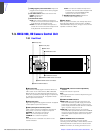
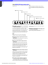
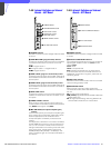
d MIC/PGM (microphone/program audio) switch
ON: To turn on the headset microphone
OFF: To turn off the headset microphone
PGM (program): To output the program audio to the
intercom connector
e Intercom volume control
To adjust the intercom input level
f Intercom line selector
Select the intercom line to which the intercom signal is
to be connected:
PROD (producer): Producer line
PRIV (private): The producer line and engineer line
are disconnected, and communication is possible
only between the HDCU-950 and the connected
camera.
ENG (engineer): Engineer line
g Intercom connector (XLR 5-pin)
Connect a headset.
Note
To use a headset with a plug other than an XLR 5-pin
plug, consult a Sony service or sales representative.
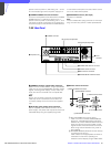
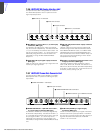
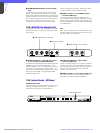
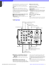
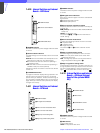
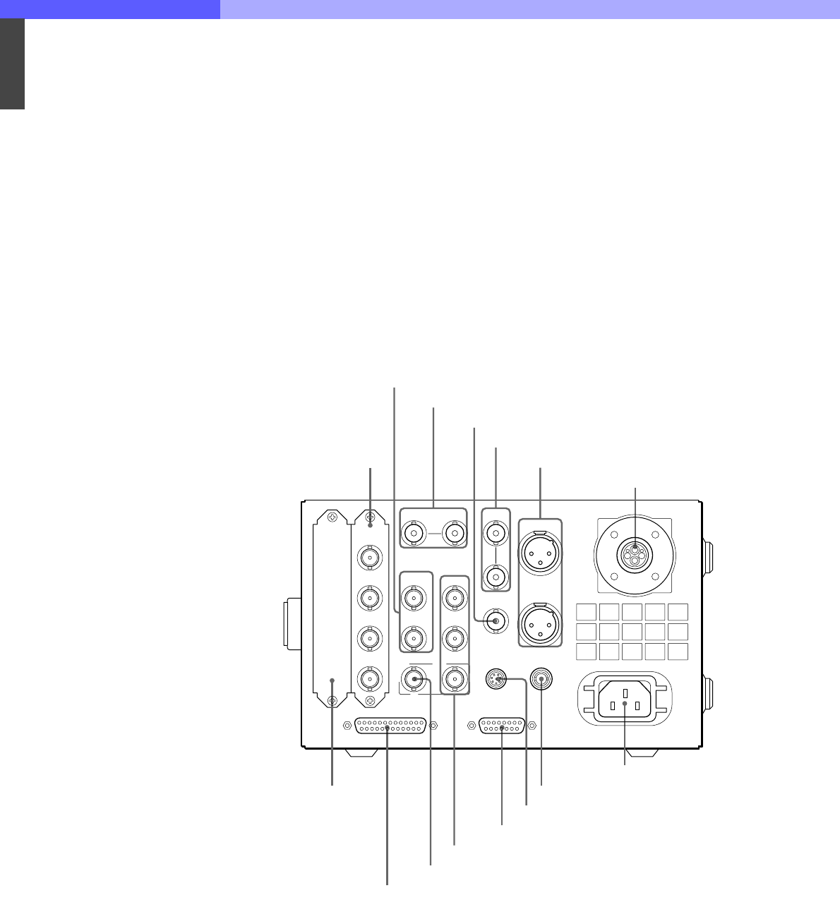
7-4-2 Rear Panel
a HD SDI OUT 1 and HD SDI OUT 2 (HD serial
digital interface output 1 and 2) connectors
(BNC type)
The signal from the video camera may be output as
HD-SDI signals.
b REFERENCE connectors (BNC type)
Input an HD tri-level reference sync signal or SD
reference sync signal (black burst signal) to either of
the two connectors. The input signal is output from the
other connector as-is (loop-through output). If loop-
through output is not used, terminate the unused
connector with 75 ohms. The type of reference signal
is selected using the switch on the internal AT board,
or using the MSU-700A/750 Master Setup Unit.
Note
To use the VBS signal of the HKCU-951 SD Encoder
Unit (SC phase lock is required), use an SD reference
sync signal (black burst signal).
REFERENCE PROMPTER
CAMERA
SYNC OUT
RCP/CNU WF MODE
INCOM/TALLY/PGM MIC REMOTE
MIC2
MIC1
HD SDI
OUT 1
HD SDI
OUT 2
RET1
RET2
MONI
RET3
RC
SD SDI
OUT 1
SD SDI
OUT 2
PIX
OUT
WF
OUT
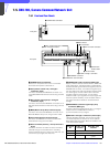
1 HD SDI OUT 1 and HD SDI OUT 2 connectors
2 REFERENCE connectors
3 SYNC OUT connector
4 PROMPTER connectors (RET4)
5 MIC1 and MIC2 connectors
6 CAMERA connector
7 Expansion slot
8 INCOM/TALLY/PGM connector
9 MONI connector
q; RET1, RET2, and RET3 connectors
qa MIC REMOTE connector (WF REMOTE)
qs RCP/CNU connector
qd WF MODE connector
qf AC IN connector
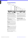
SD output block (DIF board)