


7
Chapter 7 Location and Function of Parts and Controls 102HDC-900/950/930 Series Product Information Manual
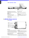
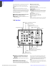
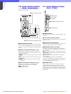
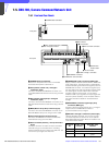
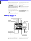
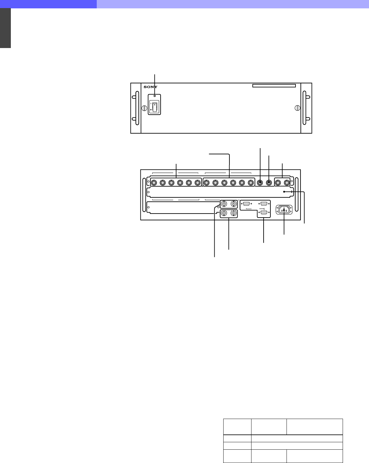
7-5. CNU-700, Camera Command Network Unit
7-5-1 Front and Rear Panels
a POWER switch and indicator
Press to turn the power ON or OFF. The indicator
illuminates when power is switched on.
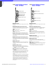
b CCU (camera control unit) 1 through 6
connectors (8-pin)
Connect to the RCP/CNU REMOTE connector on a
CCU-700A/700AP Camera Control Unit using a CCA-5
cable.
c RCP (remote control panel) 1 through 6
connectors (8-pin)
Connect to the CCU/CNU REMOTE connectors on an
RCP-700 Series Remote Control Panel using a CCA-5
cable.
d MSU (Master Set-up Unit) connector (8-pin)
Connect to the CCU/CNU REMOTE connector on an
MSU-700 Master Set-up Unit using a CCA-5 cable.
e VCS (video selector) connector (8-pin)
Connect to the REMOTE connector of a VCS-700
Video Selector using a CCA-5 cable.
f AUX1 and AUX2 (auxiliary 1 and 2) connectors
(8-pin)
Connect to the AUX1 or AUX2 connector of another
CNU-700 using a CCA-5 cable when controlling
multiple cameras with two or more CNU-700 units. You
can connect up to eight CNU-700 units.
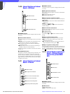
g CHARACTER 1and 2 connectors (BNC type)
Supply character data as a 525 or 625-line, black-and-
white video signal. The signal output is automatically
selected according to the reference signal input to the
REFERENCE connector. If no reference signal is input,
the CNU-700 for the USA and Canada supplies a 525-
line video signal, the CNU-700 for other countries
supplies a 625-line video signal. You can select
whether to add a sync signal to the output signal with
switch S7 (SYNC ON/OFF) on the AT board. Refer to
the system manual for details on the board switch
settings.
h REFERENCE (reference signal input) loop
connectors (BNC type)
Accepts a reference signal (VS, BS, etc.). The signal
output from the CHARACTER connector is
synchronized with the input signal.
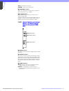
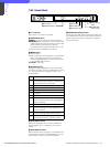
i RS-232C 1 through 3 connectors (D-sub 9-pin)
Used for RS-232C interfaces. The function of these
connectors depends on whether or not an optional
BKP-7930 System Expansion Board is installed in the
CNU-700 as shown below.
POWER
CAMERACOMMAND NETWORK UNIT
7 8 9 10 11 12
CCU
123456
RCP
123456
7 8 9 10 11 12
CCU
MSU VCS AUX1 AUX2
AUX4
~AC IN
MSC VCS
AUX3
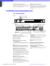
1 POWER switch and indicator
Front panel
3 RCP 1 through 6 connectors
2 CCU 1 through 6 connectors
Rear panel
4 MSU connector
5 VCS connector
6 AUX1 and AUX2 connectors
qa Optional board
insertion section
q; -AC IN connector
9 RS-232C 1 through 3 connectors
8 REFERENCE connectors
7 CHARACTER 1 and 2 connectors
Connector
No
No BKP-7930
installed
With BKP-7930
installed
1 Reserved for ISR system
2 Reserved for RS-232C interface
3 Not used
Reserved for RS-232C
system