


7
Chapter 7 Location and Function of Parts and Controls 85HDC-900/950/930 Series Product Information Manual
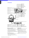
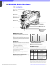
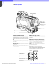
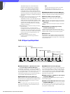
e TRACKER connector (20-pin)
Used for communication between the camera operator
and tracker and for intercom 1 and 2 connection. This
also supplied the up tally and program audio signals.
The TRUNK LINE input/output signals are also
assigned.
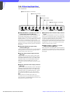
f GENLOCK IN/RET IN/PROMPTER OUT (external
gen-lock signal input/return video signal input/
prompter signal output) connector (BNC type)
and switch
Set the switch according to the signal at the connector.
GENLOCK IN: For input of an external gen-lock signal
(valid in stand-alone use only)
RET IN: For input of the return video signal (valid in
stand-alone use only)
PROMPTER OUT: Used for output of a prompter
signal (valid only when a camera control unit is
connected)
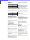
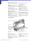
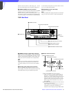
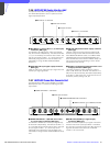
g AUDIO IN (audio input 1, 2) connectors (BNC
type) and switches
Connect audio signals. An input select switch and
microphone power switch are provided for each
channel.
A Input select switch: Set to the appropriate
position according to the connected equipment.
LINE: When a line-level signal source is
connected
MIC: When a microphone is connected
B Microphone power switch:
When a microphone is connected, set whether
or not to supply power to the microphone.
+48V: To supply a power of +48 V
OFF: Not to supply a power
Note
To supply a power of +12 V, modification of the camera
is required. For details, refer to the Installation &
Maintenance Manual. Note that the modification must
be performed by service personnel only.
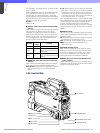
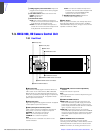
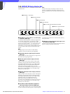
h RET CONT (return control) connector (6-pin)
Used for connection to a CAC-6 Return Video Selector.
i EXT I/O (external input and output) connector
(20-pin)
Used to supply signals, such as Y/Pb/Pr signals, to
external equipment.
j REMOTE connector (8-pin)
Used for connection to an RM-B150 Remote Control
Unit, RCP-700-series Remote Control Panel or MSU-
700A/750 Master Setup Unit.
k DC OUT (DC power supply output) connector (4-
pin)
Used to supply power to devices such as a wireless
receiver (optional).
l DC IN (DC power supply input) connector (XLR
4-pin)
Used for connection to the AC-550/550CE AC
Adaptor, a battery etc. to supply power to the camera.
m HD SERIAL OUT connector (BNC type)
Used for output of HD SDI serial data.
n VTR connector (26-pin)
Used for connection to a VTR (such as the HDW-250)
or HDCD-50 HD Signal Distributor.
LINE MIC OFF+48V
AUDIO
CH-1
IN
LINE MIC OFF+48V
CH-1
1 Input select switches
2 Microphone power switches