


7
Chapter 7 Location and Function of Parts and Controls 139HDC-900/950/930 Series Product Information Manual
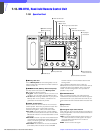
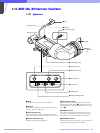
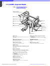
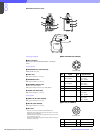
g PEAKING control
*1
Sharpens the edges in the picture. Turning the control
clockwise increases the sharpness. The peaking can
be adjusted from off to 16 dB.
h BATT (battery) indicator
This indicator blinks when the voltage output of the
camera battery drops. When the battery reaches a
point that it may no longer be used, the indicator will
light up. To prevent camera shut down due to the
battery running down, change the battery as soon as
possible after this indicator begins blinking.
The threshold battery voltage value to make this
indicator begin blinking is set by the camera. For
details, refer to the manual for the camera.
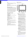
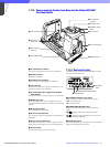
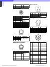
i Green tally lamps
Light up when the camera receives a green tally signal.
j Lift-lock release knob 1 (HDVF-C750W only)
Adjust the viewfinder height using lift-lock release
knob 2 p together with this knob.
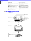
k External tally lamp
Lights up red in response to a red tally signal. Can be
used to display the camera number by attaching one
of the supplied number plates (0 through 9).
l External tally dimmer control
Adjusts the brightness of the external tally lamp. Use a
screwdriver to turn the control counterclockwise to
increase the brightness, or clockwise to dim the lamp.
m TALLY ON/OFF switch
Controls the external tally lamp k. When set to ON, the
external tally lamp will operate. When set to OFF, the
lamp will not operate (will not light in response to a tally
signal).
n Blanking marker ON/OFF switch
Turns the display of the blanking marker on and off.
o Tally dimmer switch
Adjusts the brightness of the red tally lamps c, the
green tally lamps i, the (attention) indicator b, and
the BATT (battery) indicator h on the front panel.
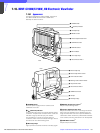
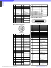
p Lift-lock release knob 2 (HDVF-C750W only)
Adjust the viewfinder height using lift-lock release
knob 1 j together with this knob.
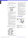
q CAMERA connector (HDVF-C750W: Round type
20-pin, HDVF-C700W: D-sub 25-pin)
HDVF-C750W: Connect to the camera’s viewfinder
connector using the supplied connecting cable.
HDVF-C700W: The CAMERA connector is on the
bottom of the viewfinder. Connect to the camera’s
viewfinder connector.
r Clamper (HDVF-C750W only)
Clamps the supplied connecting cable.
s Mounting wedge
To attach the viewfinder to a camera, the mounting
wedge is inserted into the V-shaped groove on the top
of the camera.
*1 These controls have no effect on the camera’s video output
signals.