


7
Chapter 7 Location and Function of Parts and Controls 86HDC-900/950/930 Series Product Information Manual
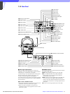
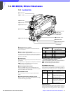
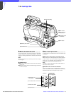
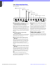
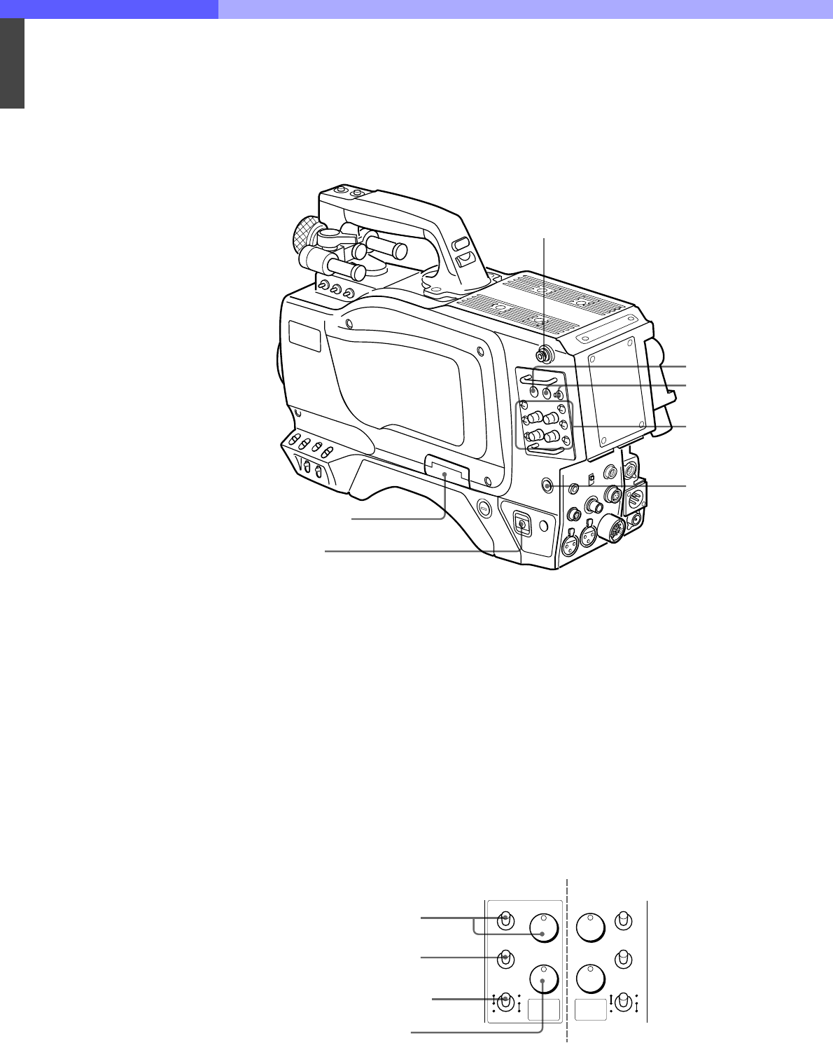
7-2-4 Back Right Side
a Memory Stick media card section
A slot to accommodate a Memory Stick media card
and an eject button to remove the stick are provided
behind the panel. The eject button lights in red while
writing or reading data to/from a Memory Stick media
card.
Note
Do not insert/remove the memory stick when the eject
button lights.
b POWER switch
CCU: Power supply will be received from the camera
control unit.
EXT: Power supply will be received through the DC IN
or VTR connector.
c RET 1 (return video 1) button
The return video 1 signal from the camera control unit
is monitored on the viewfinder screen while this button
is pressed.
d RET (return video) button and select switch
When other return video systems are used in addition
to return video 1, you can monitor the signal (return
video 2, 3, or 4) selected using the selector on the
viewfinder screen while pressing the button.
Note
The RET 1 button has priority over the RET button if
both buttons are pressed.
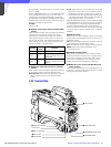
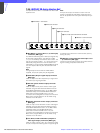
e INCOM1 and 2 controls and switches
There are a PGM control incorporated with a select
switch, a line select switch, a LEVEL/TALK switch, and
INCOM control each for intercom lines 1 and 2.
Shoulder strap fitting
1 Memory stick section
2 POWER switch
3 RET 1 button
4 RET button and
select switch
5 INCOM1/2 contr
o
and switches
6 CALL button
1 PGM control and
select switch
2 Line select switch
3 LEVEL/TALK switch
4 INCOM control
INCOM 1
INCOM 2 (same
components as
those of INCOM 1)
1
2
PROD
ENG
PGM
PGM
INCOM
2
INCOM
PGM
INCOM
1
INCOM
LEVEL
TALK
F
ON
OFF
R
LEVEL
TALK
F
ON
OFF
R
1
2
PROD
ENG
PGM