


8
Chapter 8 Connectors and Cables 162HDC-900/950/930 Series Product Information Manual
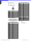
*1
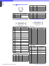
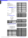
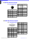
CCU1 to CCU6 Connectors
6pin . . POWER (+) IN
7pin . . POWER (–) IN
RCP1 to RCP6, AUX Connectors
6pin . . POWER (+) OUT (RCP POWER +30 V)
7pin . . POWER (–) OUT (GND for Power)
MSU/VCS Connectors
NOT USED
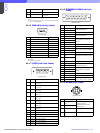
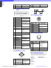
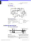
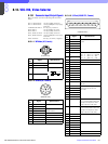
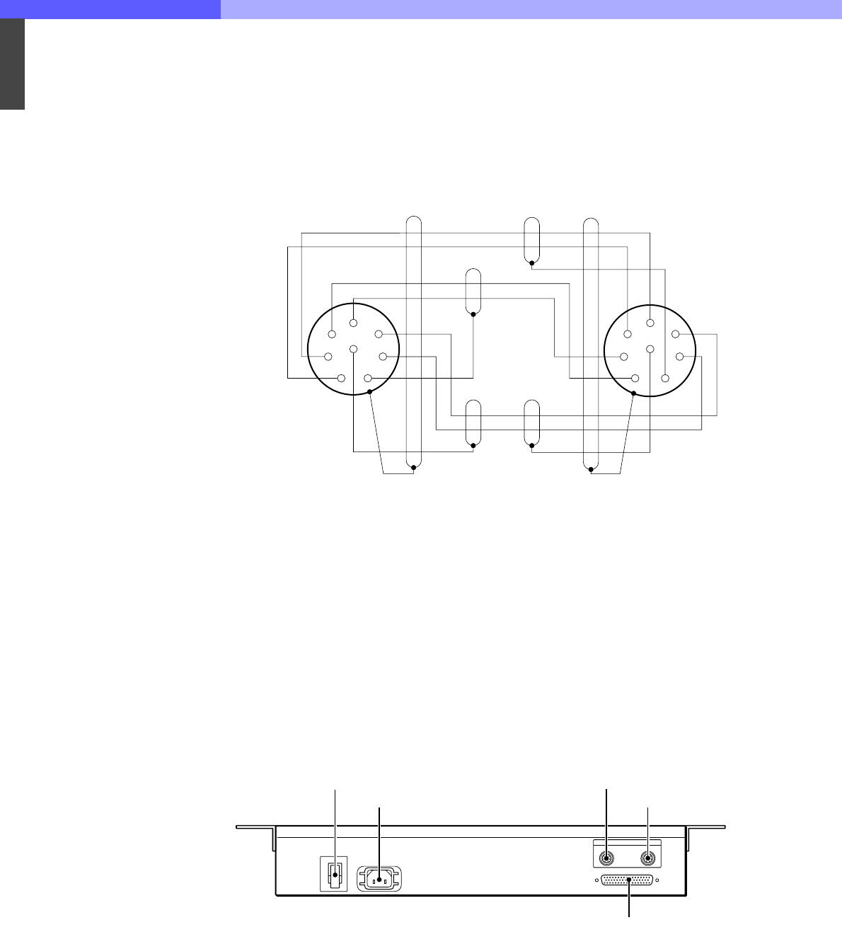
8-5-2 Cable Wiring
CCA-5 Cable (for REMOTE connector)
8-5-3 Connection Connector
Connections made with the connector panels during
installation or service should be made with the
connectors/complete cable assemblies specified in
the following list, or equivalent parts.
Connector name Connection connector/cable
REFERENCE 1-569-370-12 Connector,
BNC
CHARACTER
(BNC)
RS-232C (9P, FEMALE)
1-566-354-11
D-SUB, 9P MALE
CCU 1-766-848-11 PLUG, 8P MALE
RCP or CCA cable assembly
(option)
MSU CCA-5-10 (10 m)
VCS CCA-5-3 (3 m)
AUX (8P, FEMALE)
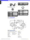
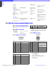
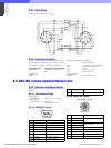
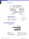
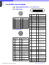
8-6. MSU-700A, Master Setup Unit
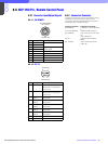
8-6-1 Connector Input/Output Signals
a POWER switch
Turns the power to the unit on and off.
b ~AC IN (AC power input) connector
Connect to an AC power source using the supplied AC
power cord. The power cord can be fixed to this unit
using the supplied plug holder.
c CCU/CNU REMOTE (camera control unit/camera
command network unit remote) connector (8-
pin)
Connect to the RCP/CNU connector of the CCU-700A/
700AP or the MSU connector of the CNU-700.
d AUX REMOTE (auxiliary remote) connector (8-
pin)
Black
White
White
Brown
White
Red
Red
Brown
Brown
Orange
1
2
3
4
8
5
6
7
1
2
3
4
8
5
6
7
POWER
I
O
I/O PORT
AUX
CCU/CNU
REMOTE
AC IN
1 POWER switch
2 AC IN connector
3 CCU/CNU REMOTE connector
4 AUX REMOTE connector
5 I/O PORT connector