


7
Chapter 7 Location and Function of Parts and Controls 83HDC-900/950/930 Series Product Information Manual
from the factory, the values set are L = 0 dB, M = 6 dB,
and H = 12 dB.
When the MESSAGE setting on the VF DISPLAY page
of the OPERATION menu is set to ON, the newly
selected gain value will be displayed in the setting
change/adjustment progress message display area of
the viewfinder screen for three seconds when the gain
setting is changed using this switch.
Example
“GAIN: 12 dB”
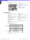
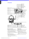
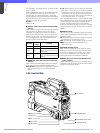
j OUTPUT (output signal selection)/AUTO KNEE
switch1)
Used to select the signal (color bar signal or camera’s
video signal) to be used as output to a VTR, the
viewfinder, or a video monitor. When the camera’s
video signal is being used as output, the auto knee
function may be used. The relationship between the
switch setting and the output signal and auto knee
function is shown in the table below.
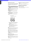
k WHITE BAL (white balance memory selection)
switch1)
Used to select the white balance adjustment method,
or the memory used to store the adjusted value.
PRST (preset): White balance is adjusted to a preset
value corresponding to a color temperature of
3200K.
A or B: Selects memory A or B. When the AUTO W/B
BAL switch is set to WHT, the white balance will be
automatically adjusted according to the setting of
the FILTER control. The adjusted value will be stored
in the selected memory. Each memory can store up
to four adjusted values, for a total of 8.
When the MESSAGE setting on the VF DISPLAY page
of the OPERATION menu is set to ON, the new setting
will be displayed in the setting change/adjustment
progress message display area of the viewfinder
screen for three seconds when the setting is changed
using this switch. Example: “WHITE: Ach” or “WHITE:
PRESET”
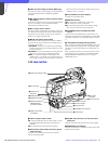
l DISPLAY switch
You can turn on or off the displays (safety zone marker,
center marker, text displays) and menu screens on the
viewfinder screen.
ON: Text describing the camera’s operation status will
be displayed on the viewfinder screen.
OFF: All viewfinder screen displays will be turned off.
MENU: Setup menus will be displayed on the
viewfinder screen.
m CANCEL/STATUS switch
When a menu is displayed on the viewfinder screen,
pressing this button will cancel any changed setting
and return the display to the previous menu. When
menus are not displayed on the viewfinder screen,
pressing this button will display the ‘!’IND item.
n MENU SEL (menu select) knob/ENTER button
(rotary encoder)
Used to select settings from menus displayed on the
viewfinder screen (by rotating the knob) and to confirm
settings (by pushing the button).
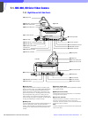
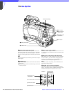
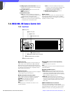
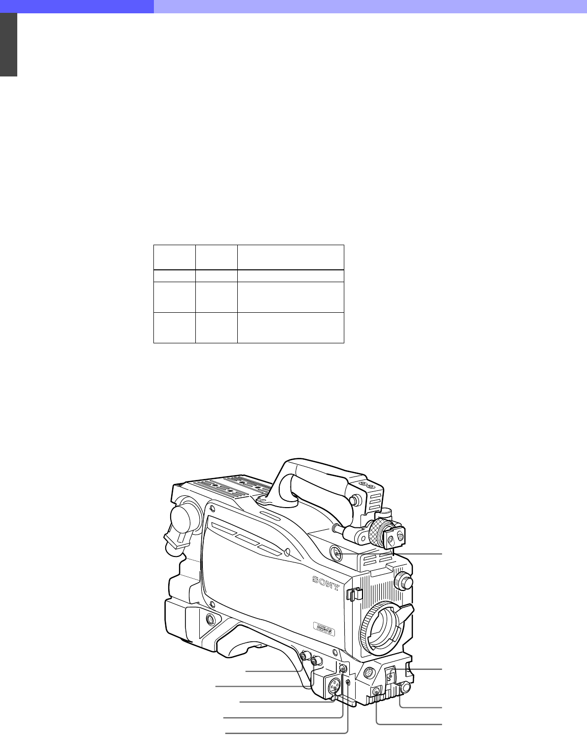
7-2-2 Front Left Side
OUTPUT
AUTO
KNEE
Function
BARS OFF Output is a color bar signal.
CAM OFF
Output is the camera’s video
signal. The auto knee circuit
is disabled.
CAM ON
Output is the camea’s video
signl. The auto knee circuit is
enable.
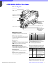
8 VTR START button
1 TEST OUT connector
2 MIC 1 IN connector
3 RET 1 button
4 MIC IN switch
5 VF connector
6 SHUTTER switch
7 INCOM/EAR LEVEL control
For future use